CYLINDER HEAD GASKET(w/o DPF) INSTALLATION

CAUTION / NOTICE / HINT
Note
-
Before performing these installation procedures, sufficiently clean and remove any foreign matter from the cylinder block, cylinder head, camshaft and other parts.
-
When replacing an injector (including interchanging injectors between cylinders), common rail, cylinder head, or intake manifold, replace the corresponding injection pipes with a new one.
PROCEDURE
-
CHECK INJECTOR COMPENSATION CODE
-
SELECT CYLINDER HEAD GASKET
-
Set the 2 crankshaft pulley set bolts to the crankshaft.
-
Clean the cylinder block with solvent.
-
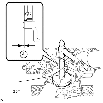
Inspect the protrusion for each cylinder.
-
Set the piston of the cylinder to be measured to slightly before TDC.
-
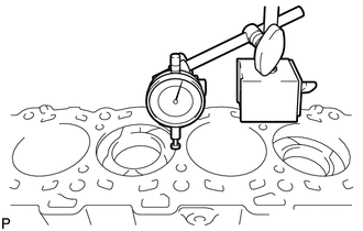
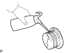
Place a dial indicator on the cylinder block, and set the measuring tip as shown in the illustration.
Note
Make sure that the dial indicator is at a right angle to the cylinder block top surface.
-
Set the dial indicator at 0 mm (0 in.).
Tech Tips
Make sure that the measuring tip is flat against the cylinder block surface and piston head when taking the measurements.
-
Find where the piston head protrudes most by slowly turning the crankshaft clockwise and counterclockwise.
-
Measure the piston protrusion value of each cylinder at 2 places as shown in the illustration below, making a total of 8 measurements.
Standard piston protrusion 0.520 to 0.780 mm (0.0205 to 0.0307 in.) If the protrusion is not as specified, remove and reinstall the piston and connecting rod.

*1 for Bank 1: *2 Front *3 for Bank 2: *4 Measuring Point
-
-
Select a new cylinder head gasket.

*1 for Bank 1: *2 for Bank 2: *3 Front Tech Tips
Cylinder head gaskets are marked A, B, C, D or E accordingly.
New Installed Cylinder Head Gasket Thickness Item Cutout Specified Condition* A 1 1.20 to 1.30 mm (0.0472 to 0.0512 in.) B 2 1.25 to 1.35 mm (0.0492 to 0.0394 in.) C 3 1.30 to 1.40 mm (0.0512 to 0.0551 in.) D 4 1.35 to 1.45 mm (0.0531 to 0.0571 in.) E 5 1.40 to 1.50 mm (0.0551 to 0.0591 in.) Tech Tips
*: The specified condition indicates the thickness of the gasket after tightening the cylinder head.
-
Select the largest piston protrusion value from the measurements and then select a new appropriate gasket according to the table below.
Standard Piston Protrusion Item Specified Condition A 0.520 to 0.575 mm (0.0205 to 0.0226 in.) B 0.575 to 0.625 mm (0.0226 to 0.0246 in.) C 0.625 to 0.675 mm (0.0246 to 0.0266 in.) D 0.675 to 0.725 mm (0.0266 to 0.0285 in.) E 0.725 to 0.780 mm (0.0285 to 0.0307 in.)
-
-
-
INSTALL NO. 2 CYLINDER HEAD GASKET
-

*1 Front *2 Exhaust Side Remove any oil from the contact surface.
-
Place the cylinder head gasket on the cylinder block surface with the front face of the indicated mark "L" upward and facing the exhaust side.
-
-
INSTALL NO. 1 CYLINDER HEAD GASKET
-

*1 Exhaust Side *2 Front Remove any oil from the contact surface.
-
Place the cylinder head gasket on the cylinder block surface with the front face of the indicated mark "R" upward and facing the exhaust side.
-
-
INSTALL CYLINDER HEAD SUB-ASSEMBLY LH
-
Place the cylinder head on the cylinder head gasket.
Note
Ensure that no oil is on the mounting surface of the cylinder head.
-
Inspect the cylinder head bolts Click here.
-
Apply a light coat of engine oil to the threads and under the heads of the cylinder head bolts.
-
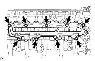
Step 1:
-
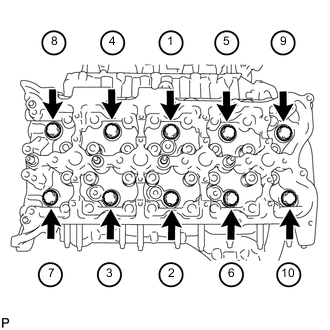
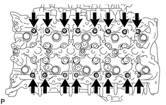
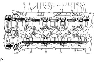
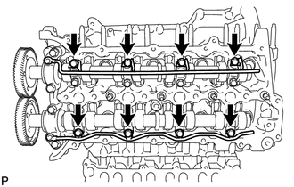
Install and uniformly tighten the 10 cylinder head bolts with the spacers in several steps, in the sequence shown in the illustration.
- Torque:
- 80 N*m { 816 kgf*cm, 59 ft.*lbf }
Tech Tips
-
The cylinder head bolts are tightened in 4 progressive steps.
-
If a cylinder head bolt is broken or deformed, replace it.
-
-

*1 Front *2 Painted Mark Step 2:
-
Mark the cylinder head bolt heads with paint as shown in the illustration.
-
Tighten the cylinder head bolts 90° in the sequence shown in step 1.
-
-

*1 Painted Mark *2 Front Step 3:
-
Tighten the cylinder head bolts another 90° in the sequence shown in step 1.
-
-
*1 Painted Mark *2 Front Step 4:
-
Tighten the cylinder head bolts by an additional 90° in the sequence shown in step 1.
-
-
Check that the painted marks are now facing the exhaust port side.
-
-
INSTALL CYLINDER HEAD SUB-ASSEMBLY RH
-
Place the cylinder head on the cylinder head gasket.
Note
Ensure that no oil is on the mounting surface of the cylinder head.
-
Inspect the cylinder head bolts Click here.
-
Apply a light coat of engine oil to the threads and under the heads of the cylinder head bolts.
-
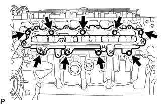
Step 1:
-
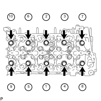
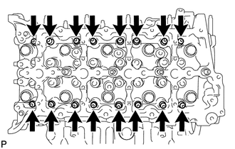
Install and uniformly tighten the 10 cylinder head bolts with the spacers in several steps, in the sequence shown in the illustration.
- Torque:
- 80 N*m { 816 kgf*cm, 59 ft.*lbf }
Tech Tips
-
The cylinder head bolts are tightened in 4 progressive steps.
-
If a cylinder head bolt is broken or deformed, replace it.
-
-
*1 Front *2 Painted Mark Step 2:
-
Mark the cylinder head bolt heads with paint as shown in the illustration.
-
Tighten the cylinder head bolts 90° in the sequence shown in step 1.
-
-

*1 Painted Mark *2 Front Step 3:
-
Tighten the cylinder head bolts another 90° in the sequence shown in step 1.
-
-
*1 Painted Mark *2 Front Step 4:
-
Tighten the cylinder head bolts by an additional 90° in the sequence shown in step 1.
-
-
Check that the painted marks are now facing the intake port side.
-
-
SET NO. 1 CYLINDER TO 45° BEFORE TDC
-
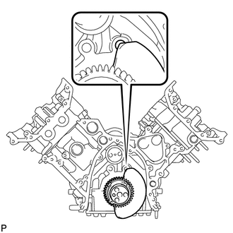
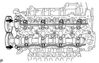
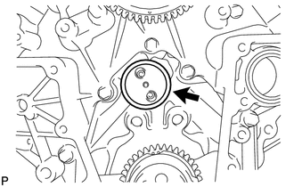
Using a bar, turn the crankshaft counterclockwise until the No. 1 cylinder is at a position 45° before TDC.
Note
Do not turn the crankshaft again until after the timing gear is installed.
Tech Tips
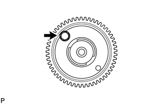
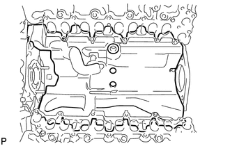
The No. 1 cylinder is at a position 45° before TDC if the crankshaft counterweight is overlapping the cylinder block hole as shown in the illustration.
-
Remove the 2 crankshaft pulley set bolts.
-
-
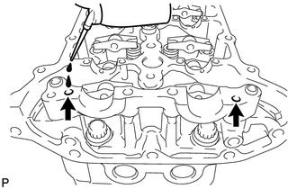
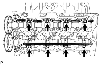
INSTALL NO. 2 VALVE LASH ADJUSTER ASSEMBLY
Note
Be sure to inspect the valve lash adjuster before installing it Click here.
-
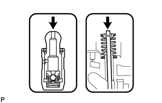
Install the 16 No. 2 valve lash adjusters to the cylinder head.
Tech Tips
Install the lash adjuster at the same place it was removed from.
-
-
INSTALL NO. 1 VALVE LASH ADJUSTER ASSEMBLY
Note
Be sure to inspect the valve lash adjuster before installing it Click here.
-
Install the 16 No. 1 valve lash adjusters to the cylinder head.
Tech Tips
Install the lash adjuster at the same place it was removed from.
-
-
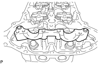
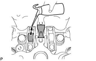
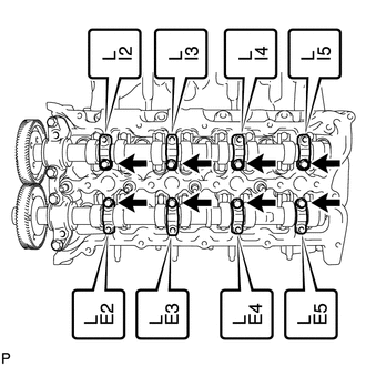
INSTALL NO. 2 VALVE ROCKER ARM
-
Apply engine oil to the lash adjuster tips and valve stem ends.
-
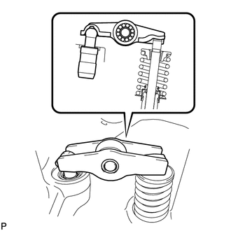
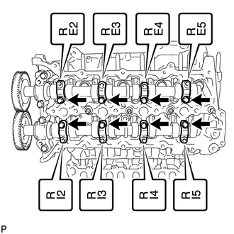
Install the 16 No. 2 valve rocker arms as shown in the illustration.
Tech Tips
Install the valve rocker arm at the same place it was removed from.
-
-
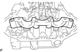
INSTALL NO. 1 VALVE ROCKER ARM
-
Apply engine oil to the lash adjuster tips and valve stem ends.
-
Install the 16 No. 1 valve rocker arms as shown in the illustration.
Tech Tips
Install the valve rocker arm at the same place it was removed from.
-
-
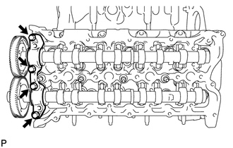
INSTALL NO. 5 CAMSHAFT BEARING CAP
-
Align the camshaft bearing cap and the ring pins of the cylinder head, and install the cap.
-
-
INSTALL NO. 2 CAMSHAFT BEARING CAP
-
Align the camshaft bearing cap and the ring pins of the cylinder head, and install the cap.
-
-
INSTALL NO. 3 AND NO. 4 CAMSHAFTS
-
Add more than 19 cc (1.16 cu. in.) of engine oil into the cylinder head side oil holes.
-
Apply engine oil to the rollers of the valve rocker arms and the camshaft housing of the cylinder head.
-
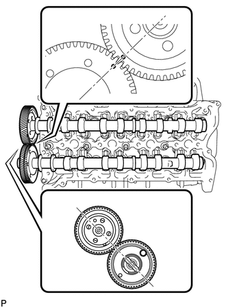
Install the camshafts.
-
Apply engine oil to the camshaft journals, lobes, thrust portion and gears.
-
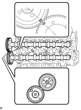
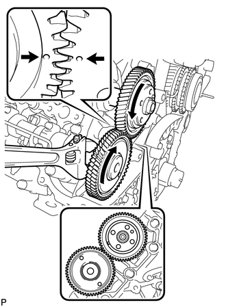
Align the timing marks (1 dot mark) on the back side of the No. 3 and No. 4 camshaft timing gears as shown in the illustration.
-
Place the camshafts into the cylinder head.
Note
Before and after setting the camshafts, firmly set the rocker arms to the lash adjusters.
-
-
Install the No. 4 camshaft bearing cap.
-
Align the No. 4 camshaft bearing cap and the ring pins of the No. 5 camshaft bearing cap.
-
Temporarily install the 4 bolts by hand.
-
-
Install the No. 3 camshaft bearing caps.
-
Confirm the marks and numbers on the camshaft bearing caps and place them in their proper position and direction.
-
Temporarily install the 8 bolts, which are not installed with the oil feed pipe, by hand.
-
-
Temporarily install the No. 3 and No. 4 camshaft oil feed pipes with the 8 bolts by hand.
Note
If even one of the pipe bolt holes does not match its camshaft bearing cap bolt hole, replace the camshaft oil feed pipe.
Tech Tips
The pipe is bent on the intake side, and straight on the exhaust side.
-
Temporarily install the 2 union bolts by hand.
-

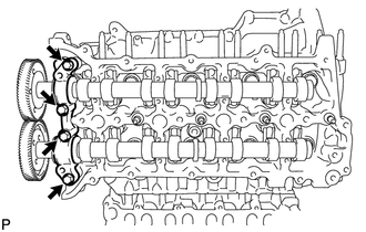
*a 12 mm Head Bolt *b 10 mm Head Bolt Uniformly tighten the 20 bolts in several steps in the order shown in the illustration.
- Torque:
- for 12 mm head bolt of No. 4 camshaft bearing cap
- 21 N*m { 214 kgf*cm, 15 ft.*lbf }
- for 10 mm head bolt of No. 3 camshaft bearing cap
- 10 N*m { 102 kgf*cm, 7 ft.*lbf }
-
Tighten the 2 union bolts.
- Torque:
- 17 N*m { 173 kgf*cm, 13 ft.*lbf }
-
Remove the bolt from the No. 4 camshaft timing gear.
Note
Do not drop the bolt into the engine.
-
-
INSTALL NO. 1 AND NO. 2 CAMSHAFT
-
Add more than 19 cc (1.16 cu. in.) of engine oil into the cylinder head side oil holes.
-
Apply engine oil to the rollers of the valve rocker arms and the camshaft housing of the cylinder head.
-
Install the camshafts.
-
Apply engine oil to the camshaft journals, lobes, thrust portion and gears.
-
Align the timing marks (2 dot marks) on the back side of the No. 1 and No. 2 camshaft timing gears as shown in the illustration.
-
Place the camshafts into the cylinder head.
Note
Before and after setting the camshafts, firmly set the rocker arms to the lash adjusters.
-
-
Install the No. 1 camshaft bearing cap.
-
Align the No. 1 camshaft bearing cap and the ring pins of the No. 2 camshaft bearing cap.
-
Temporarily install the 4 bolts by hand.
-
-
Install the No. 3 camshaft bearing caps.
-
Confirm the marks and numbers on the camshaft bearing caps and place them in their proper position and direction.
-
Temporarily install the 8 bolts, which are not installed with the oil feed pipe, by hand.
-
-
Temporarily install the No. 1 and No. 2 camshaft oil feed pipes with the 8 bolts by hand.
Note
If even one of the pipe bolt holes does not match its camshaft bearing cap bolt hole, replace the camshaft oil feed pipe.
Tech Tips
The pipe is bent on the intake side, and straight on the exhaust side.
-
Temporarily install the 2 union bolts by hand.
-

*a 12 mm Head Bolt *b 10 mm Head Bolt Uniformly tighten the 20 bolts in several steps in the order shown in the illustration.
- Torque:
- for 12 mm head bolt of No. 1 camshaft bearing cap
- 21 N*m { 214 kgf*cm, 15 ft.*lbf }
- for 10 mm head bolt of No. 3 camshaft bearing cap
- 10 N*m { 102 kgf*cm, 7 ft.*lbf }
-
Tighten the 2 union bolts.
- Torque:
- 17 N*m { 173 kgf*cm, 13 ft.*lbf }
-
Remove the bolt from the No. 1 camshaft timing gear.
Note
Do not drop the bolt into the engine.
-
-
INSTALL TIMING GEAR CASE SUB-ASSEMBLY
-
Apply seal packing to the timing gear case as shown in the following illustration.
Standard seal diameter 4 to 5 mm (0.157 to 0.197 in.) Seal packing Toyota Genuine Seal Packing Black, Three Bond 1207B or equivalent Note
-
After applying seal packing, align the timing gear case with the engine within 3 minutes and tighten the bolts and nuts within 15 minutes.
-
Apply the seal packing in a continuous line.
Tech Tips
-
The FIPG line is shown below.
-
Apply packing to the 5 seal surface areas.

*1 2.5 mm (0.0984 in.) *2 2.0 mm (0.0787 in.) *3 Seal Diameter: 4 to 5 mm -
-

*1 New Timing Gear Case Gasket *2 New O-Ring Install a new timing gear case gasket.
-
Apply engine oil to 2 new O-rings and install them to the timing gear case.
-

*1 Nut *2 14 mm Head Bolt *3 12 mm Head Bolt A *4 12 mm Head Bolt B Install the timing gear case with the 22 bolts and 2 nuts.
- Torque:
- for 14 mm head bolt (case is dry)
- 46 N*m { 469 kgf*cm, 34 ft.*lbf }
- for 14 mm head bolt (case is wet)
- 42 N*m { 428 kgf*cm, 31 ft.*lbf }
- for 12 mm head bolt A and B
- 29 N*m { 296 kgf*cm, 21 ft.*lbf }
- for nut
- 29 N*m { 296 kgf*cm, 21 ft.*lbf }
Note
-
The case is "dry" when there is absolutely no engine oil on the 14 mm head bolts and cylinder head bolt holes.
-
The case is "wet" when there is engine oil on the 14 mm head bolts and cylinder head bolt holes.
Bolt Length Item Quantity Length A 4 20 mm (0.787 in.) B 8 45 mm (1.77 in.)
-
-
INSTALL V-BANK SILENCER
-
Align the alignment areas of the V-bank silencer and cylinder block, and install the V-bank silencer.
Note
Verify that the V-bank silencer is below the top surface of the intake port of the cylinder head RH and LH.
-
-
INSTALL FUEL SUPPLY PUMP ASSEMBLY
-
Using an 8 mm x 1.25 pitch tap, remove the adhesive from the timing gear case side bolt hole.
-

*1 Adhesive Apply adhesive to 2 or more threads of the timing gear case bolt hole.
Adhesive Toyota Genuine Adhesive 1344, Three Bond 1344 or equivalent -

*1 New O-Ring Apply engine oil to a new O-ring and install it to the supply pump.
-
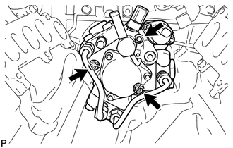
Install the supply pump to the timing gear case.
Note
When installing the supply pump, do not hold the fuel pipe to prevent fuel leaks.
-
Temporarily install the 2 nuts.
-
Using a 6 mm hexagon wrench, install the hexagon bolt, and then tighten the 2 nuts.
- Torque:
- 21 N*m { 214 kgf*cm, 15 ft.*lbf }
-
-
-
INSPECT RADIAL BALL BEARING
-
TEMPORARILY INSTALL FUEL SUPPLY PUMP DRIVE GEAR
-
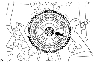
Align the cutout of the supply pump drive gear and key of the supply pump, and temporarily install the nut.
-
-
SET NO. 1 AND NO. 2 CAMSHAFTS TO TDC
-
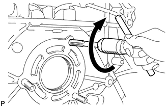
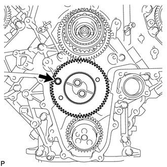
Using a wrench, turn the No. 1 camshaft and align the timing marks (1 dot mark) on the back side of the timing gears as shown in the illustration.
-
-
INSTALL NO. 1 IDLE GEAR SHAFT
-
Apply engine oil to the contact surface of the idle gear shaft and the back side of the protrusion.
-
Install the idle gear shaft to the cylinder block.
-
-
INSTALL IDLE GEAR ASSEMBLY
-

*1 Key Temporarily install the 2 crankshaft pulley set bolts to the crankshaft.
-
Using a bar, turn the crankshaft clockwise to the No. 1 cylinder TDC position.
-
Align the timing marks of the supply pump drive gear and idle gear, and the timing marks of the crankshaft timing gear and idle gear as shown in the illustration.

*1 w/ Intercooler: *2 w/o Intercooler: -
Apply engine oil to the idle gear thrust plate and gears.
-

*1 w/ Intercooler: *2 w/o Intercooler: Install the idle gear thrust plate with the 2 bolts.
- Torque:
- 47 N*m { 479 kgf*cm, 35 ft.*lbf }
-
w/ Intercooler:
Remove the service bolt.
-
-
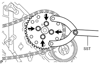
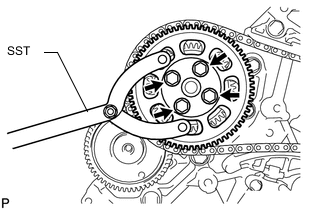
TIGHTEN FUEL SUPPLY PUMP DRIVE GEAR NUT
-
Using SST, hold the idle gear and tighten the nut.
- SST
- 09960-10010 ( 09962-01000, 09963-00700 )
- Torque:
- 68 N*m { 693 kgf*cm, 50 ft.*lbf }

*1 w/ Intercooler: *2 w/o Intercooler:
-
-
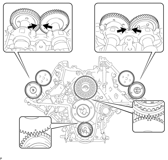
CHECK NO. 1 CYLINDER TO TDC/COMPRESSION
-
Check that the timing marks of the following pairs of parts are aligned: 1) supply pump drive gear and idle gear: 2) crankshaft timing gear and idle gear: 3) RH and LH camshaft timing gears.
-
-
INSTALL NO. 2 CAMSHAFT TIMING SPROCKET AND NO. 2 TIMING CHAIN
-
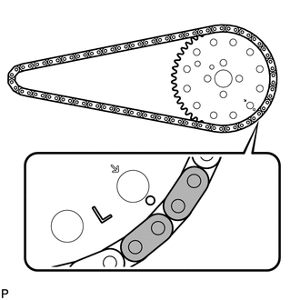
Align the 2 mark plates (yellow) on the No. 2 timing chain with the timing mark (1 dot mark) of the No. 2 camshaft timing sprocket as shown in the illustration.
-

*1 Timing Mark Align the No. 2 timing chain mark plate (yellow) with the supply pump drive gear timing mark, and temporarily install the No. 2 camshaft timing sprocket with the 4 bolts.
-
Using SST, hold the No. 2 camshaft timing sprocket, and tighten the 4 bolts.
- SST
- 09960-10010 ( 09962-01000, 09963-01000 )
- Torque:
- 25 N*m { 250 kgf*cm, 18 ft.*lbf }
-
-
INSTALL NO. 1 CAMSHAFT TIMING SPROCKET AND NO. 1 TIMING CHAIN
-
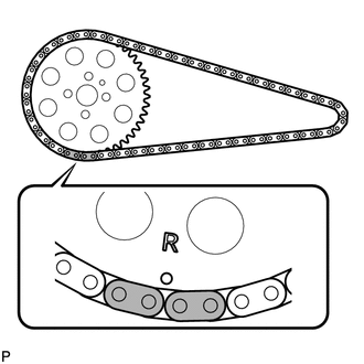
Align the 2 mark plates (yellow) on the No. 1 timing chain with the timing mark (1 dot mark) of the No. 1 camshaft timing sprocket as shown in the illustration.
-

*1 Timing Mark Align the No. 1 timing chain mark plate (yellow) with the supply pump drive gear timing mark, and temporarily install the No. 1 camshaft timing sprocket.
-
-
INSTALL PUMP DRIVE SHAFT GEAR
-
Temporarily install the pump drive shaft gear with the 4 bolts.
-
Using SST, hold the pump drive shaft gear and tighten the 4 bolts.
- SST
- 09960-10010 ( 09962-01000, 09963-01000 )
- Torque:
- 25 N*m { 250 kgf*cm, 18 ft.*lbf }
-
-
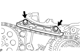
INSTALL NO. 2 CHAIN VIBRATION DAMPER
-
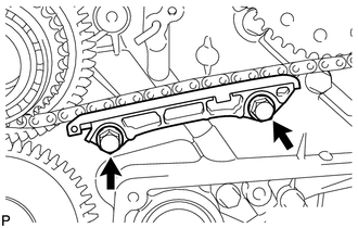
Install the No. 2 chain vibration damper with the 2 bolts.
- Torque:
- 21 N*m { 214 kgf*cm, 15 ft.*lbf }
-
-
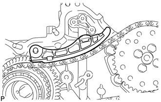
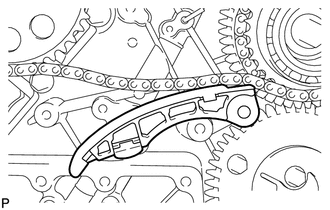
INSTALL NO. 2 CHAIN TENSIONER SLIPPER
-
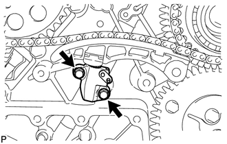
INSTALL NO. 2 CHAIN TENSIONER ASSEMBLY
-
Move the stopper plate clockwise to release the lock, and push the plunger into the tensioner.
-
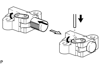
Move the stopper plate counterclockwise to set the lock, and insert a hexagon wrench into the stopper plate hole.
-
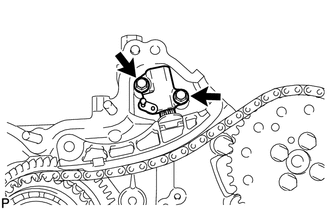
Install the No. 2 chain tensioner with the 2 bolts.
- Torque:
- 10 N*m { 102 kgf*cm, 7 ft.*lbf }
-
Remove the hexagon wrench.
-
-
INSTALL NO. 1 CHAIN VIBRATION DAMPER
-
Install the No. 1 chain vibration damper with the 2 bolts.
- Torque:
- 21 N*m { 214 kgf*cm, 15 ft.*lbf }
-
-
INSTALL NO. 1 CHAIN TENSIONER SLIPPER
-
INSTALL NO. 1 CHAIN TENSIONER ASSEMBLY
-
Move the stopper plate clockwise to release the lock, and push the plunger into the tensioner.
-
Move the stopper plate counterclockwise to set the lock, and insert a hexagon wrench into the stopper plate hole.
-
Install the No. 1 chain tensioner with the 2 bolts.
- Torque:
- 10 N*m { 102 kgf*cm, 7 ft.*lbf }
-
Remove the hexagon wrench.
-
-
INSTALL NO. 1 CRANKSHAFT POSITION SENSOR PLATE
-

Remove the adhesive from the threads of the screws and the bolt holes of the crankshaft.
-
Apply adhesive to 2 or 3 threads of the 2 screws.
Adhesive Toyota Genuine Adhesive 1344, Three Bond 1344 or equivalent -
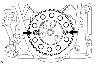
Using a T30 "TORX" wrench, install the No. 1 crankshaft position sensor plate with the 2 screws.
- Torque:
- 10 N*m { 102 kgf*cm, 7 ft.*lbf }
Note
Make sure the "F" mark on the plate is facing towards the front side of the engine.
-
-
CHECK NO. 1 CYLINDER TO TDC/COMPRESSION
-
Temporarily install the 2 crankshaft pulley set bolts to the crankshaft.
-
Rotate the crankshaft 2 revolutions or more so that the crankshaft key is 45° counterclockwise from the top. Check that the timing marks (1 dot mark each) of the RH and LH camshaft timing gears align. If not as specified, turn the crankshaft 1 revolution (360°) and align the timing marks. If the timing marks are deviated, reinstall the chain and camshaft.

*1 Top *2 Key -
Remove the 2 crankshaft pulley set bolts.
-
-
INSTALL FRONT CRANKSHAFT OIL SEAL
-
Place the timing chain cover on wooden blocks.
-
Using SST and a hammer, tap in a new oil seal as shown in the illustration.
- SST
- 09316-12010
- 09950-70010 ( 09951-07100 )
- 09950-60020 ( 09951-00890 )
Standard depth A 0.6 to 1.4 mm (0.0236 to 0.0551 in.)
-
-
INSTALL TIMING CHAIN COVER SUB-ASSEMBLY
-

*1 New O-ring Install a new O-ring to the timing gear case.
-
Apply seal packing to the timing chain cover as shown in the following illustration.
Standard seal diameter 4 to 5 mm (0.157 to 0.197 in.) Seal packing Toyota Genuine Seal Packing Black, Three Bond 1207B or equivalent Note
-
After applying seal packing, align the timing chain cover with the timing gear case within 3 minutes and tighten the bolts and nuts within 15 minutes.
-
Apply the seal packing in a continuous line.
-
Make sure the seal packing does not become thinner than 4 mm (0.157 in.) at the areas labeled "B" in the illustration below.
-
-
Apply engine oil to the lip of the oil seal.
-
Align and install the timing chain cover to the timing gear case knock pin and supply pump bearing.
Note
Make sure that the lip of the oil seal is properly installed.
- Torque:
- 25 N*m { 250 kgf*cm, 18 ft.*lbf }
-
Using an E7 "TORX" wrench, tighten the stud bolts.
- Torque:
- 6.0 N*m { 61 kgf*cm, 53 in.*lbf }
-

*a Nut Install and uniformly tighten the 16 bolts and 4 nuts in the order shown in the illustration.
-
-
TEMPORARILY INSTALL INTAKE MANIFOLD
-
Install the gasket and temporarily install the No. 2 intake manifold with the 9 bolts.
-
Install the gasket and temporarily install the No. 1 intake manifold with the 9 bolts.
-

Install the 2 gaskets and temporarily install the No. 3 intake manifold with the 16 bolts.
Bolt Length Item Length Bolt A 70 mm (2.76 in.) Bolt B 25 mm (0.984 in.)
-
-
TEMPORARILY INSTALL COMMON RAIL ASSEMBLY RH
-
TEMPORARILY INSTALL COMMON RAIL ASSEMBLY LH
-
INSTALL FUEL INJECTOR RH
-
INSTALL FUEL INJECTOR LH
-
REMOVE COMMON RAIL ASSEMBLY RH
-
REMOVE COMMON RAIL ASSEMBLY LH
-
REMOVE INTAKE MANIFOLD
-

Remove the 16 bolts, 2 gaskets and intake manifold.
-
Remove the 9 bolts, No. 1 intake manifold and gasket.
-
Remove the 9 bolts, No. 2 intake manifold and gasket.
-
-
INSTALL NOZZLE HOLDER GASKET LH
-
INSTALL CYLINDER HEAD COVER SUB-ASSEMBLY LH
-
INSTALL NOZZLE HOLDER SEAL LH
-
INSTALL OIL SEPARATOR ASSEMBLY
-
INSTALL NOZZLE HOLDER GASKET RH
-
INSTALL CYLINDER HEAD COVER SUB-ASSEMBLY RH
-
INSTALL NOZZLE HOLDER SEAL RH
-
INSTALL CYLINDER HEAD COVER SILENCER LH (w/ Intercooler)
-
INSTALL CYLINDER HEAD COVER SILENCER RH (w/ Intercooler)
-
INSTALL VACUUM PUMP ASSEMBLY (w/ Intercooler)
-
INSTALL NO. 1 VACUUM TRANSMITTING PIPE SUB-ASSEMBLY
-
INSTALL NO. 1 VACUUM SWITCHING VALVE ASSEMBLY (w/ Intercooler)
-
INSTALL GLOW PLUG ASSEMBLY
-
INSTALL NO. 1 GLOW PLUG CONNECTOR
-
INSTALL WATER OUTLET PIPE
-
INSTALL WATER OUTLET
-
INSTALL NO. 2 INTERCOOLER SUPPORT BRACKET
-
INSTALL CLUTCH FLEXIBLE HOSE BRACKET (for Manual Transmission)
-

Install the clutch flexible hose bracket with the 2 bolts.
- Torque:
- 20 N*m { 204 kgf*cm, 15 ft.*lbf }
-
-
INSTALL STARTER HOSE BRACKET
-

Install the starter hose bracket with the 2 bolts.
- Torque:
- 10 N*m { 102 kgf*cm, 7 ft.*lbf }
-
-
INSTALL STARTER ASSEMBLY
-
INSTALL WATER PUMP ASSEMBLY
-
CONNECT INLET WATER HOSE
-
INSTALL NO. 2 IDLER PULLEY BRACKET (w/ Viscous Heater)
-
INSTALL NO. 2 IDLER PULLEY (w/ Viscous Heater)
-
INSTALL FAN BRACKET SUB-ASSEMBLY
-
INSTALL TIMING GEAR COVER INSULATOR (w/ Intercooler)
-
INSTALL THERMOSTAT
-
INSTALL WATER INLET
-
INSTALL NO. 1 IDLER PULLEY BRACKET (w/ Viscous Heater)
-
INSTALL VISCOUS HEATER ASSEMBLY WITH MAGNET CLUTCH (w/ Viscous Heater)
-
INSTALL CRANKSHAFT POSITION SENSOR
-
INSTALL CAMSHAFT POSITION SENSOR
-
INSTALL NO. 1 OIL PAN SUB-ASSEMBLY
-
INSTALL OIL STRAINER SUB-ASSEMBLY
-
INSTALL NO. 2 OIL PAN SUB-ASSEMBLY
-
INSTALL ENGINE OIL LEVEL SENSOR
-
INSTALL OIL FILTER BRACKET SUB-ASSEMBLY
-
INSTALL OIL FILTER ELEMENT
-
INSTALL TIMING GEAR COVER SPACER (w/ Intercooler)
-
INSTALL CRANKSHAFT PULLEY
-
CONNECT NO. 2 OIL COOLER HOSE
-
CONNECT NO. 1 OIL COOLER HOSE
-
INSTALL V-RIBBED BELT TENSIONER ASSEMBLY
-
INSTALL STIFFENER INSULATOR RH (w/ Intercooler)
-
INSTALL COMPRESSOR BRACKET
-
INSTALL NO. 2 CYLINDER BLOCK INSULATOR
-
INSTALL ENGINE MOUNTING BRACKET LH
-
INSTALL NO. 2 WATER BY-PASS PIPE SUB-ASSEMBLY
-
INSTALL NO. 3 VACUUM TRANSMITTING PIPE SUB-ASSEMBLY
-
INSTALL TURBOCHARGER WIRE
-
INSTALL NO. 2 INTAKE AIR CONNECTOR BRACKET
-
INSTALL NO. 1 CYLINDER BLOCK INSULATOR
-
INSTALL ENGINE MOUNTING BRACKET RH
-
INSTALL NO. 4 VACUUM TRANSMITTING PIPE SUB-ASSEMBLY (w/ Intercooler)
-
INSTALL NO. 1 WATER BY-PASS PIPE SUB-ASSEMBLY
-
INSTALL AIR TUBE SUPPORT
-
INSTALL NO. 1 INTAKE AIR CONNECTOR BRACKET
-
INSTALL NO. 2 TURBOCHARGER SUB-ASSEMBLY WITH EXHAUST MANIFOLD LH
-
INSTALL NO. 2 VENTILATION TUBE SUB-ASSEMBLY
-
INSTALL NO. 2 TURBOCHARGER STAY
-
CONNECT NO. 2 OUTLET TURBO OIL HOSE
-
INSTALL NO. 2 TURBO WATER PIPE SUB-ASSEMBLY
-
INSTALL FRONT WATER BY-PASS JOINT
-
INSTALL NO. 3 TURBO WATER PIPE SUB-ASSEMBLY
-
INSTALL NO. 2 EXHAUST MANIFOLD HEAT INSULATOR
-
CONNECT NO. 2 TURBO WATER HOSE
-
CONNECT BREATHER PLUG LH
-
CONNECT NO. 3 VENTILATION HOSE
-
INSTALL NO. 1 TURBOCHARGER SUB-ASSEMBLY WITH EXHAUST MANIFOLD RH
-
INSTALL NO. 1 VENTILATION TUBE SUB-ASSEMBLY
-
INSTALL NO. 1 TURBOCHARGER STAY
-
INSTALL NO. 1 TURBO WATER PIPE SUB-ASSEMBLY
-
CONNECT NO. 1 OUTLET TURBO OIL HOSE
-
INSTALL NO. 1 EXHAUST MANIFOLD HEAT INSULATOR
-
CONNECT NO. 2 TURBO WATER HOSE
-
CONNECT BREATHER PLUG RH
-
CONNECT NO. 2 VENTILATION HOSE
-
INSTALL GENERATOR ASSEMBLY
-
INSTALL NO. 1 INTAKE AIR CONNECTOR PIPE
-
INSTALL NO. 1 ENGINE OIL LEVEL DIPSTICK GUIDE
-
INSTALL ENGINE ASSEMBLY
-
Install the engine assembly to the vehicle Click here.
-
-
CONNECT CABLE TO NEGATIVE BATTERY TERMINAL
Note
When disconnecting the cable, some systems need to be initialized after the cable is reconnected Click here.
-
Connect the cables to the negative (-) main battery and sub-battery terminals.
-