CYLINDER HEAD GASKET(w/ DPF) INSTALLATION
CAUTION / NOTICE / HINT
Note
-
Before performing these installation procedures, sufficiently clean and remove any foreign matter from the cylinder block, cylinder head, camshaft and other parts.
-
When replacing an injector (including interchanging injectors between cylinders), common rail, cylinder head, or intake manifold, replace the corresponding injection pipes with a new one.
-
When fuel lines are disconnected, air may enter the fuel lines, leading to engine starting trouble. Therefore, perform forced regeneration and bleed the air from the fuel lines Click here.
PROCEDURE
-
CHECK INJECTOR COMPENSATION CODE
-
SELECT CYLINDER HEAD GASKET
-
Set the 2 crankshaft pulley set bolts to the crankshaft.
-
Clean the cylinder block with solvent.
-
Inspect the protrusion for each cylinder.
-
Set the piston of the cylinder to be measured to slightly before TDC.
-
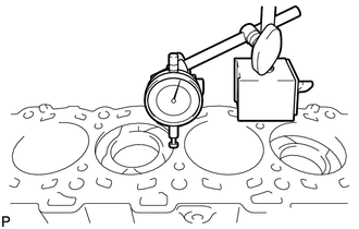
Place a dial indicator on the cylinder block, and set the measuring tip as shown in the illustration.
Note
Make sure that the dial indicator is at a right angle to the cylinder block top surface.
-
Set the dial indicator at 0 mm (0 in.).
Tech Tips
Make sure that the measuring tip is flat against the cylinder block surface and piston head when taking the measurements.
-
Find where the piston head protrudes most by slowly turning the crankshaft clockwise and counterclockwise.
-
Measure the piston protrusion value of each cylinder at 2 places as shown in the illustration below, making a total of 8 measurements.
Standard piston protrusion 0.520 to 0.780 mm (0.0205 to 0.0307 in.) If the protrusion is not as specified, remove and reinstall the piston and connecting rod.
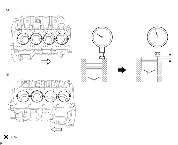
Text in Illustration *A for Bank 1 *B for Bank 2 *a Measuring Point - - 
Front - -
-
-
Select a new cylinder head gasket.
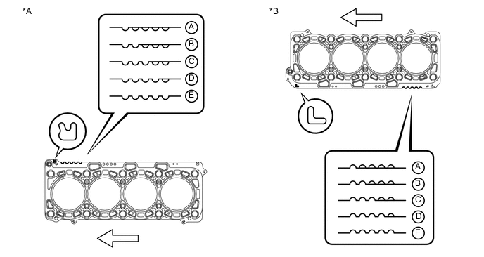
Text in Illustration *A for Bank 1 *B for Bank 2 Front - - Tech Tips
Cylinder head gaskets are marked A, B, C, D or E accordingly.
New Installed Cylinder Head Gasket Thickness Item Cutout Specified Condition* A 1 1.20 to 1.30 mm (0.0472 to 0.0512 in.) B 2 1.25 to 1.35 mm (0.0492 to 0.0394 in.) C 3 1.30 to 1.40 mm (0.0512 to 0.0551 in.) D 4 1.35 to 1.45 mm (0.0531 to 0.0571 in.) E 5 1.40 to 1.50 mm (0.0551 to 0.0591 in.) Tech Tips
*: The specified condition indicates the thickness of the gasket after tightening the cylinder head.
-
Select the largest piston protrusion value from the measurements and then select a new appropriate gasket according to the table below.
Standard Piston Protrusion Item Specified Condition A 0.520 to 0.575 mm (0.0205 to 0.0226 in.) B 0.575 to 0.625 mm (0.0226 to 0.0246 in.) C 0.625 to 0.675 mm (0.0246 to 0.0266 in.) D 0.675 to 0.725 mm (0.0266 to 0.0285 in.) E 0.725 to 0.780 mm (0.0285 to 0.0307 in.)
-
-
-
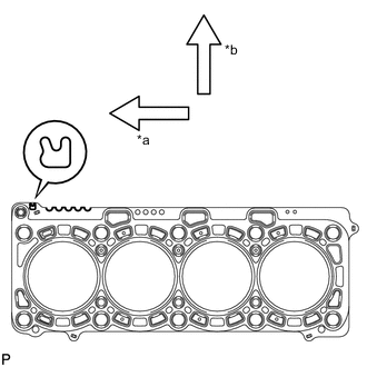
INSTALL NO. 2 CYLINDER HEAD GASKET
-
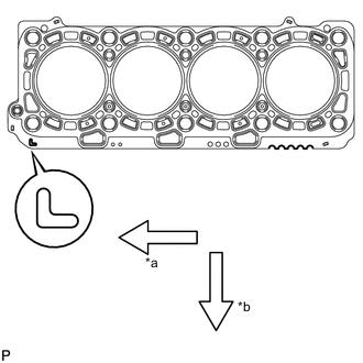
Text in Illustration *a Front *b Exhaust Side Remove any oil from the contact surface.
-
Place the cylinder head gasket on the cylinder block surface with the front face of the indicated mark "L" upward and facing the exhaust side.
-
-
INSTALL NO. 1 CYLINDER HEAD GASKET
-
Text in Illustration *a Front *b Exhaust Side Remove any oil from the contact surface.
-
Place the cylinder head gasket on the cylinder block surface with the front face of the indicated mark "R" upward and facing the exhaust side.
-
-
INSTALL CYLINDER HEAD SUB-ASSEMBLY LH
-
INSTALL CYLINDER HEAD SUB-ASSEMBLY RH
-
SET NO. 1 CYLINDER TO 45° BEFORE TDC
-
INSTALL NO. 2 VALVE LASH ADJUSTER ASSEMBLY
-
INSTALL NO. 1 VALVE LASH ADJUSTER ASSEMBLY
-
INSTALL NO. 2 VALVE ROCKER ARM
-
INSTALL NO. 1 VALVE ROCKER ARM
-
INSTALL NO. 5 CAMSHAFT BEARING CAP
-
INSTALL NO. 2 CAMSHAFT BEARING CAP
-
INSTALL NO. 3 AND NO. 4 CAMSHAFTS
-
INSTALL NO. 1 AND NO. 2 CAMSHAFT
-
INSTALL TIMING GEAR CASE SUB-ASSEMBLY
-
INSTALL V-BANK SILENCER
-
INSTALL FUEL SUPPLY PUMP ASSEMBLY
-
INSTALL FUEL PUMP MOTOR WIRE
-
INSPECT RADIAL BALL BEARING
-
TEMPORARILY INSTALL FUEL SUPPLY PUMP DRIVE GEAR
-
SET NO. 1 AND NO. 2 CAMSHAFTS TO TDC
-
INSTALL NO. 1 IDLE GEAR SHAFT
-
INSTALL IDLE GEAR ASSEMBLY
-
TIGHTEN FUEL SUPPLY PUMP DRIVE GEAR NUT
-
CHECK NO. 1 CYLINDER TO TDC/COMPRESSION
-
INSTALL NO. 2 CAMSHAFT TIMING SPROCKET AND NO. 2 TIMING CHAIN
-
INSTALL NO. 1 CAMSHAFT TIMING SPROCKET AND NO. 1 TIMING CHAIN
-
INSTALL PUMP DRIVE SHAFT GEAR
-
INSTALL NO. 2 CHAIN VIBRATION DAMPER
-
INSTALL NO. 2 CHAIN TENSIONER SLIPPER
-
INSTALL NO. 2 CHAIN TENSIONER ASSEMBLY
-
INSTALL NO. 1 CHAIN VIBRATION DAMPER
-
INSTALL NO. 1 CHAIN TENSIONER SLIPPER
-
INSTALL NO. 1 CHAIN TENSIONER ASSEMBLY
-
INSTALL NO. 1 CRANKSHAFT POSITION SENSOR PLATE
-
CHECK NO. 1 CYLINDER TO TDC/COMPRESSION
-
INSTALL FRONT CRANKSHAFT OIL SEAL
-
INSTALL TIMING CHAIN COVER SUB-ASSEMBLY
-
INSTALL FUEL INJECTOR SEAL
-
INSTALL EXHAUST FUEL ADDITION INJECTOR ASSEMBLY
-
TEMPORARILY INSTALL INTAKE MANIFOLD
-
INSTALL CYLINDER HEAD COVER SUB-ASSEMBLY LH
-
INSTALL CYLINDER HEAD COVER SUB-ASSEMBLY RH
-
INSTALL FUEL INJECTOR LH
-
INSTALL FUEL INJECTOR RH
-
REMOVE INTAKE MANIFOLD
-
INSTALL CYLINDER HEAD COVER INSULATOR LH
-
INSTALL CYLINDER HEAD COVER INSULATOR RH
-
INSTALL NO. 2 FUEL PUMP BRACKET
-
INSTALL OIL SEPARATOR ASSEMBLY
-
INSTALL VACUUM PUMP ASSEMBLY
-
INSTALL GLOW PLUG ASSEMBLY
-
INSTALL NO. 1 GLOW PLUG CONNECTOR
-
INSTALL WATER OUTLET PIPE
-
INSTALL WATER OUTLET
-
INSTALL NO. 2 INTERCOOLER SUPPORT BRACKET
-
INSTALL STARTER HOSE BRACKET
-
Install the starter hose bracket with the 2 bolts.
- Torque:
- 10 N*m { 102 kgf*cm, 7 ft.*lbf }
-
-
INSTALL STARTER ASSEMBLY
-
INSTALL WATER PUMP ASSEMBLY
-
CONNECT INLET WATER HOSE
-
INSTALL NO. 2 IDLER PULLEY BRACKET (w/ Viscous Heater)
-
INSTALL NO. 2 IDLER PULLEY (w/ Viscous Heater)
-
INSTALL FAN BRACKET SUB-ASSEMBLY
-
INSTALL TIMING GEAR COVER INSULATOR
-
INSTALL THERMOSTAT
-
INSTALL WATER INLET
-
INSTALL NO. 1 IDLER PULLEY BRACKET (w/ Viscous Heater)
-
INSTALL VISCOUS HEATER ASSEMBLY WITH MAGNET CLUTCH (w/ Viscous Heater)
-
INSTALL CRANKSHAFT POSITION SENSOR
-
INSTALL CAMSHAFT POSITION SENSOR
-
INSTALL NO. 1 OIL PAN SUB-ASSEMBLY
-
INSTALL OIL STRAINER SUB-ASSEMBLY
-
INSTALL NO. 2 OIL PAN SUB-ASSEMBLY
-
INSTALL ENGINE OIL LEVEL SENSOR
-
INSTALL OIL FILTER BRACKET SUB-ASSEMBLY
-
INSTALL OIL FILTER ELEMENT
-
INSTALL TIMING GEAR COVER SPACER
-
INSTALL CRANKSHAFT PULLEY
-
CONNECT NO. 2 OIL COOLER HOSE
-
CONNECT NO. 1 OIL COOLER HOSE
-
INSTALL V-RIBBED BELT TENSIONER ASSEMBLY
-
INSTALL STIFFENER INSULATOR RH
-
INSTALL COMPRESSOR BRACKET
-
INSTALL NO. 2 CYLINDER BLOCK INSULATOR
-
INSTALL ENGINE MOUNTING BRACKET LH
-
INSTALL NO. 2 WATER BY-PASS PIPE SUB-ASSEMBLY
-
INSTALL NO. 3 VACUUM TRANSMITTING PIPE SUB-ASSEMBLY
-
INSTALL TURBOCHARGER WIRE
-
INSTALL NO. 2 INTAKE AIR CONNECTOR BRACKET
-
INSTALL NO. 1 CYLINDER BLOCK INSULATOR
-
INSTALL ENGINE MOUNTING BRACKET RH
-
INSTALL NO. 4 VACUUM TRANSMITTING PIPE SUB-ASSEMBLY
-
INSTALL NO. 1 WATER BY-PASS PIPE SUB-ASSEMBLY
-
INSTALL AIR TUBE SUPPORT
-
INSTALL NO. 1 INTAKE AIR CONNECTOR BRACKET
-
INSTALL GENERATOR ASSEMBLY
-
INSTALL NO. 1 TURBOCHARGER SUB-ASSEMBLY WITH EXHAUST MANIFOLD RH AND NO. 2 TURBOCHARGER SUB-ASSEMBLY WITH EXHAUST MANIFOLD LH
-
CONNECT CABLE TO NEGATIVE BATTERY TERMINAL
Note
When disconnecting the cable, some systems need to be initialized after the cable is reconnected Click here.
-
Connect the cables to the negative (-) main battery and sub-battery terminals.
-