PROCEDURE
- Click here
INSTALL FUEL INJECTOR SEAL (w/ DPF)
- Click here
INSTALL EXHAUST FUEL ADDITION INJECTOR ASSEMBLY (w/ DPF)
- Click here
INSTALL COMPRESSOR BRACKET
-
Install the compressor bracket with the bolt.
21 N*m 214 kgf*cm 15 ft.*lbf
-
- Click here
INSTALL V-RIBBED BELT TENSIONER ASSEMBLY
- Click here
INSTALL STIFFENER INSULATOR RH (w/ Intercooler)
- Click here
INSTALL OIL PRESSURE REGULATOR ASSEMBLY
-
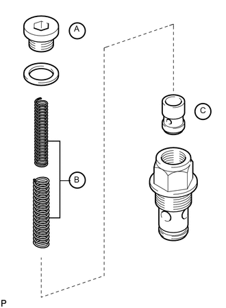
Hold the oil pressure regulator body in a vise between aluminum plates.
-
Apply a light coat of engine oil to the oil pump relief valve labeled C.
-
Install the oil pump relief valve labeled C to the oil pressure regulator body.
-
Install the 2 springs labeled B to the oil pressure regulator body.
-
Using a 10 mm hexagon wrench, install a new gasket and the oil pump relief valve plug labeled A.
50 N*m 510 kgf*cm 37 ft.*lbf -
Apply a light coat of engine oil to a new O-ring, and install it to the oil pressure regulator body.
-
Using a 26 mm wrench, install a new gasket and the oil pressure regulator.
86 N*m 877 kgf*cm 63 ft.*lbf
-
- Click here
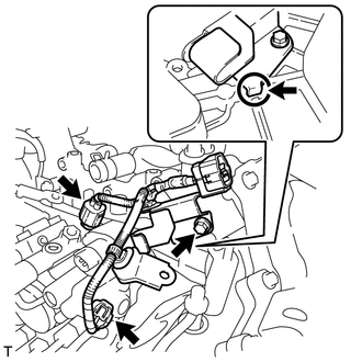
INSTALL OIL FILTER BRACKET DRAIN COCK ASSEMBLY
-
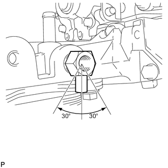
Install the drain cock.
20 N*m 204 kgf*cm 15 ft.*lbf -
Using a 17 mm wrench, rotate the drain cock clockwise (360°) and align the position of the drain hole so that it is within the range shown in the illustration after tightening the drain cock to the specified torque.
Note:
-
As the oil filter bracket may be damaged, the maximum tightening torque should be 80 N*m (816 kgf*cm, 59 ft.*lbf) or less.
-
Do not rotate the drain cock more than 1 revolution (360°) after tightening the drain cock with the specified torque.
-
Do not expose the drain cock to coolant within 1 hour after installation.
-
-
Install the oil filter drain cock plug.
13 N*m 130 kgf*cm 9 ft.*lbf
-
- Click here
INSTALL OIL TANK BRACKET
-
Install the oil tank bracket with the bolt.
10 N*m 102 kgf*cm 7 ft.*lbf
-
- Click here
INSTALL NO. 2 CYLINDER BLOCK INSULATOR
- Click here
INSTALL ENGINE MOUNTING BRACKET LH
-
Install the engine mounting bracket LH with the 4 bolts.
80 N*m 816 kgf*cm 59 ft.*lbf
-
- Click here
INSTALL NO. 2 WATER BY-PASS PIPE SUB-ASSEMBLY
-
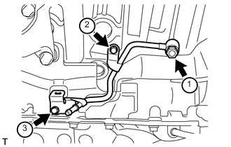
Temporarily install a new gasket and No. 2 water by-pass pipe with the union bolt and 2 bolts.
-
Tighten the union bolt and 2 bolts of the No. 2 water by-pass pipe in the order shown in the illustration.
for union bolt 35 N*m 357 kgf*cm 26 ft.*lbf for bolt 10 N*m 102 kgf*cm 7 ft.*lbf
-
- Click here
INSTALL NO. 3 VACUUM TRANSMITTING PIPE SUB-ASSEMBLY
-
Install the No. 3 vacuum transmitting pipe with the 2 bolts.
6.0 N*m 61 kgf*cm 53 in.*lbf -
w/ Intercooler:
Connect the vacuum hose.
-
- Click here
INSTALL TURBOCHARGER WIRE
-
Install the turbocharger wire with the 2 bolts.
21 N*m 214 kgf*cm 15 ft.*lbf -
Attach the 3 wire harness clamps.
-
- Click here
INSTALL NO. 2 INTAKE AIR CONNECTOR BRACKET
-
Install the No. 2 intake air connector bracket with the bolt.
21 N*m 214 kgf*cm 15 ft.*lbf -
Attach the 2 wire clamps.
-
- Click here
INSTALL NO. 1 CYLINDER BLOCK INSULATOR
- Click here
INSTALL ENGINE MOUNTING BRACKET RH
-
Install the engine mounting bracket RH with the 4 bolts.
80 N*m 816 kgf*cm 59 ft.*lbf
-
- Click here
INSTALL NO. 4 VACUUM TRANSMITTING PIPE SUB-ASSEMBLY (w/ Intercooler)
-
Install the No. 4 vacuum transmitting pipe with the 2 bolts.
6.0 N*m 61 kgf*cm 53 in.*lbf -
Connect the vacuum hose.
-
- Click here
INSTALL NO. 1 WATER BY-PASS PIPE SUB-ASSEMBLY
-
Temporarily install a new gasket and the No. 1 water by-pass pipe with the union bolt and bolt.
-
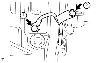
Tighten the union bolt and bolt of the No. 1 water by-pass pipe in the order shown in the illustration.
for union bolt 35 N*m 357 kgf*cm 26 ft.*lbf for bolt 10 N*m 102 kgf*cm 7 ft.*lbf
-
- Click here
INSTALL AIR TUBE SUPPORT
-
Install the air tube support with the 2 bolts.
21 N*m 214 kgf*cm 15 ft.*lbf
-
- Click here
INSTALL NO. 1 INTAKE AIR CONNECTOR BRACKET
-
Install the No. 1 intake air connector bracket with the 2 bolts.
21 N*m 214 kgf*cm 15 ft.*lbf
-
- Click here
INSTALL REAR CYLINDER HEAD PLATE LH (w/o EGR System)
-
Install a new gasket and the rear cylinder head plate LH with the 2 bolts.
29 N*m 296 kgf*cm 21 ft.*lbf Tip:The gasket claw should face toward the plate.
-
- Click here
INSTALL REAR CYLINDER HEAD PLATE RH (w/o EGR System)
-
Install a new gasket and the rear cylinder head plate RH with the 2 bolts.
29 N*m 296 kgf*cm 21 ft.*lbf Tip:The gasket claw should face toward the plate.
-
- Click here
INSTALL CYLINDER HEAD COVER SILENCER LH (w/o DPF)
-
w/ Intercooler:
Install the cylinder head cover silencer LH with the 3 bolts.
5.0 N*m 51 kgf*cm 44 in.*lbf
-
- Click here
INSTALL CYLINDER HEAD COVER SILENCER RH (w/o DPF)
-
w/ Intercooler:
Install the cylinder head cover silencer RH with the 3 bolts.
5.0 N*m 51 kgf*cm 44 in.*lbf
-
- Click here
INSTALL NO. 1 VACUUM TRANSMITTING PIPE SUB-ASSEMBLY (w/o DPF)
- Click here
INSTALL NO. 1 VACUUM SWITCHING VALVE ASSEMBLY (w/o DPF)
- Click here
INSTALL FAN BRACKET SUB-ASSEMBLY
- Click here
INSTALL NO. 2 IDLER PULLEY BRACKET (w/ Viscous Heater)
- Click here
INSTALL NO. 2 IDLER PULLEY (w/ Viscous Heater)
- Click here
INSTALL NO. 3 ENGINE HANGER
-
Install the No. 3 engine hanger with the 2 bolts.
43 N*m 438 kgf*cm 32 ft.*lbf
-
- Click here
INSTALL NO. 1 INTERCOOLER SUPPORT BRACKET
-
Install the No. 1 intercooler support bracket with the 2 bolts.
21 N*m 214 kgf*cm 15 ft.*lbf
-
- Click here
INSTALL FUEL PUMP MOTOR WIRE
-
Install the fuel pump wire with the bolt.
6.0 N*m 61 kgf*cm 53 in.*lbf Tip:Attach the claw of the bracket to the timing gear case when installing the bracket.
-
- Click here
INSTALL GLOW PLUG ASSEMBLY
- Click here
INSTALL NO. 1 GLOW PLUG CONNECTOR
- Click here
INSTALL CLUTCH FLEXIBLE HOSE BRACKET (for Manual Transmission)
-
Install the clutch flexible hose bracket with the 2 bolts.
20 N*m 204 kgf*cm 15 ft.*lbf
-
- Click here
INSTALL NO. 1 AND NO. 2 WATER OUTLET PIPES AND WATER BY-PASS OUTLET
-
Align the painted mark of the No. 1 water hose joint with the protrusion of the water by-pass outlet and connect the water by-pass outlet to the No. 1 water hose joint.
-
Align the painted mark of the No. 1 water hose joint with the painted mark of the No. 2 water outlet pipe and connect the No. 2 water outlet pipe to the No. 1 water hose joint.
-
Connect a new gasket and the No. 1 and No. 2 water outlet pipes with the 2 bolts.
21 N*m 214 kgf*cm 15 ft.*lbf Tip:The gasket claws can face the No. 1 or No. 2 water outlet pipe.
-
- Click here
INSTALL WATER OUTLET PIPE
-
Install 2 new gaskets and the water outlet pipe with the 4 bolts.
21 N*m 214 kgf*cm 15 ft.*lbf Tip:The gasket claw should face toward the water outlet pipe.
-
- Click here
INSTALL WATER OUTLET
-
Install a new gasket and the water outlet with the 2 bolts, and then connect the water outlet to the No. 2 water hose joint.
21 N*m 214 kgf*cm 15 ft.*lbf
-
- Click here
INSTALL NO. 2 INTERCOOLER SUPPORT BRACKET
-
Install the No. 2 intercooler support bracket with the 2 bolts.
43 N*m 438 kgf*cm 32 ft.*lbf
-
- Click here
INSTALL DIESEL ENGINE COOLANT TEMPERATURE SENSOR
- Click here
CONNECT INLET WATER HOSE
- Click here
INSTALL STARTER HOSE BRACKET
- Click here
INSTALL STARTER ASSEMBLY
- Click here
INSTALL TIMING GEAR COVER INSULATOR (w/ Intercooler)
-
w/o Viscous Heater:
Install the timing gear cover insulator with the 2 bolts.
21 N*m 214 kgf*cm 15 ft.*lbf -
w/ Viscous Heater:
Install the timing gear cover insulator.
-
- Click here
INSTALL THERMOSTAT
- Click here
INSTALL WATER INLET
- Click here
INSTALL NO. 1 IDLER PULLEY BRACKET (w/ Viscous Heater)
- Click here
INSTALL VISCOUS HEATER ASSEMBLY WITH MAGNET CLUTCH (w/ Viscous Heater)
- Click here
INSTALL NO. 2 TURBOCHARGER SUB-ASSEMBLY WITH EXHAUST MANIFOLD LH
- Click here
INSTALL NO. 2 VENTILATION TUBE SUB-ASSEMBLY
- Click here
INSTALL NO. 2 TURBOCHARGER STAY
- Click here
CONNECT NO. 2 OUTLET TURBO OIL HOSE
- Click here
INSTALL NO. 2 TURBO WATER PIPE SUB-ASSEMBLY
- Click here
INSTALL FRONT WATER BY-PASS JOINT
- Click here
INSTALL NO. 3 TURBO WATER PIPE SUB-ASSEMBLY
- Click here
INSTALL NO. 2 EXHAUST MANIFOLD HEAT INSULATOR
- Click here
INSTALL NO. 2 TURBO WATER HOSE
- Click here
INSTALL BREATHER PLUG LH
- Click here
INSTALL NO. 3 VENTILATION HOSE
- Click here
INSTALL NO. 1 TURBOCHARGER SUB-ASSEMBLY WITH EXHAUST MANIFOLD RH
- Click here
INSTALL NO. 1 VENTILATION TUBE SUB-ASSEMBLY
- Click here
INSTALL NO. 1 TURBOCHARGER STAY
- Click here
INSTALL NO. 1 TURBO WATER PIPE SUB-ASSEMBLY
- Click here
CONNECT NO. 1 OUTLET TURBO OIL HOSE
- Click here
INSTALL NO. 1 EXHAUST MANIFOLD HEAT INSULATOR
- Click here
INSTALL NO. 2 TURBO WATER HOSE
- Click here
INSTALL BREATHER PLUG RH
- Click here
INSTALL NO. 2 VENTILATION HOSE
- Click here
INSTALL GENERATOR ASSEMBLY
- Click here
INSTALL NO. 1 INTAKE AIR CONNECTOR PIPE
- Click here
INSTALL NO. 1 ENGINE OIL LEVEL DIPSTICK GUIDE
- Click here
INSTALL VACUUM PUMP ASSEMBLY (w/ Intercooler)