ENGINE UNIT DISASSEMBLY

CAUTION / NOTICE / HINT
CAUTION:
When replacing an injector (including interchanging injectors between cylinders), common rail, cylinder head, or intake manifold, replace the corresponding injection pipes with a new one.
PROCEDURE
-
REMOVE CAMSHAFT POSITION SENSOR
-
REMOVE CRANKSHAFT POSITION SENSOR
-
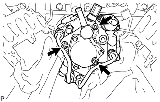
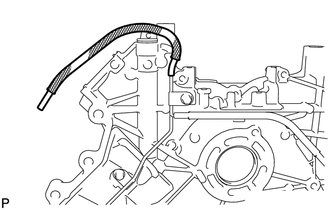
DISCONNECT NO. 1 OIL COOLER HOSE
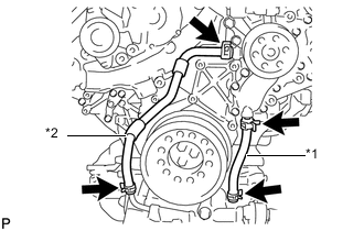
Text in Illustration *1 No. 1 Oil Cooler Hose *2 No. 2 Oil Cooler Hose -
DISCONNECT NO. 2 OIL COOLER HOSE
-
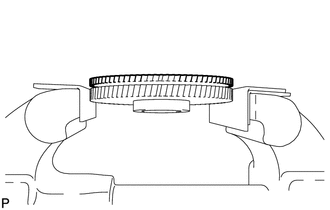
REMOVE CRANKSHAFT PULLEY
Note
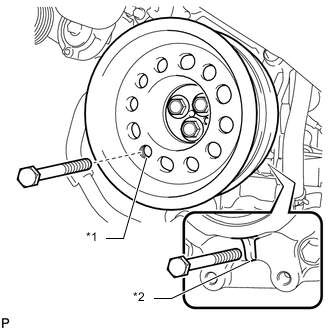
This procedure is intended for removal/installation of the crankshaft pulley only. Do not use this procedure for removal/installation of the flywheel or the drive plate and ring gear.
Text in Illustration *1 Service Hole *2 Protrusion
-
Install the 2 bolts to the bolt holes of the crankshaft rear side.
-
Using a bar, turn the crankshaft until the crankshaft pulley service hole is a little to the left of bottom dead center.
-
Install a 14 mm x 1.5 pitch service bolt with a length of 70 mm or more to the crankshaft pulley service hole, and hold the crankshaft using the timing chain cover protrusion.
-
Remove the 3 bolts and crankshaft pulley.
Note
If the crankshaft pulley cannot be removed, temporarily install a bolt to the crankshaft so that the pulley does not fall, and lightly tap the outer edge of the mass damper with a plastic-faced hammer to remove the pulley. Do not tap the pulley V-ribbed belt ribs, as the crankshaft may be damaged.
-
-
REMOVE TIMING GEAR COVER SPACER (w/ Intercooler)
-
REMOVE OIL FILTER CAP WITH ELEMENT
-
REMOVE OIL PRESSURE SENDER GAUGE ASSEMBLY
-
REMOVE OIL COOLER ASSEMBLY
-
REMOVE OIL COOLER RELIEF VALVE ASSEMBLY
-
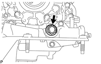
Remove the oil cooler relief valve and gasket.
-
-
REMOVE OIL FILTER BRACKET SUB-ASSEMBLY
-
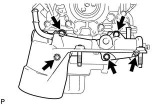
Remove the 3 bolts, 2 nuts and oil filter bracket.
-
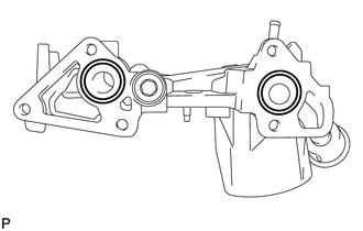
Remove the 2 O-rings.
-
-
REMOVE ENGINE OIL LEVEL SENSOR
-
REMOVE OIL PAN DRAIN PLUG
-
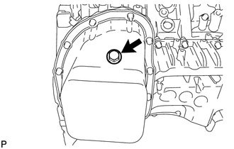
Remove the oil pan drain plug and gasket.
-
-
REMOVE NO. 2 OIL PAN SUB-ASSEMBLY
-
REMOVE OIL STRAINER SUB-ASSEMBLY
-
REMOVE NO. 1 OIL PAN SUB-ASSEMBLY
-
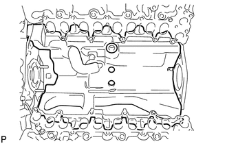
REMOVE NO. 1 OIL PAN BAFFLE PLATE
-
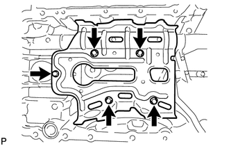
Remove the 5 bolts and No. 1 oil pan baffle plate.
-
-
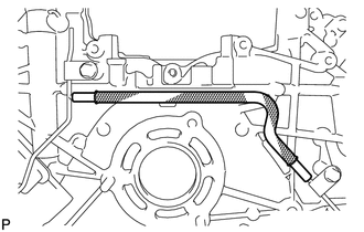
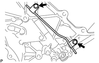
REMOVE INLET OIL PUMP PIPE
-
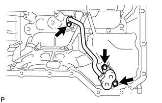
Remove the 3 bolts and inlet oil pump pipe.
-
Remove the O-ring from the inlet oil pump pipe.
-
-
REMOVE OIL REGULATOR ASSEMBLY
-
REMOVE REAR ENGINE OIL SEAL RETAINER
-
REMOVE REAR CRANKSHAFT OIL SEAL
-
Place the oil seal retainer on wooden blocks.
-
Using a screwdriver and hammer, tap out the oil seal.
Tech Tips
Tape the screwdriver tip before use.
-
-
REMOVE OIL PUMP ASSEMBLY
-
REMOVE SCAVENGING PUMP ASSEMBLY
-
REMOVE OIL FILLER CAP SUB-ASSEMBLY

-
REMOVE OIL FILLER CAP GASKET
-
REMOVE CYLINDER HEAD COVER SUB-ASSEMBLY RH (w/o DPF)
-
REMOVE NOZZLE HOLDER GASKET RH (w/o DPF)
-
REMOVE NOZZLE HOLDER SEAL RH (w/o DPF)
-
REMOVE CYLINDER HEAD COVER INSULATOR RH (w/ DPF)
-
REMOVE FUEL INJECTOR RH (w/ DPF)
-
REMOVE CYLINDER HEAD COVER SUB-ASSEMBLY RH (w/ DPF)
-
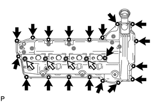
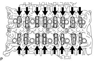
Remove the 19 bolts, 4 nozzle holder clamp seats and cylinder head cover RH.
Text in Illustration 
Bolt 
Nozzle Holder Clamp Seat -
Remove the cylinder head cover gasket RH and No. 3 cylinder head cover gasket from the cylinder head cover RH.
-
-
REMOVE NO. 2 FUEL PUMP BRACKET (w/ DPF)
-
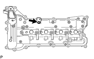
Remove the bolt and No. 2 fuel pump bracket.
-
-
REMOVE CYLINDER HEAD COVER INSULATOR LH (w/ DPF)
-
REMOVE FUEL INJECTOR LH (w/ DPF)
-
REMOVE OIL SEPARATOR ASSEMBLY
-
REMOVE CYLINDER HEAD COVER SUB-ASSEMBLY LH (w/ DPF)
-
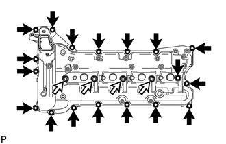
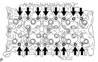
Remove the 18 bolts, 4 nozzle holder clamp seats and cylinder head cover LH.
Text in Illustration Bolt Nozzle Holder Clamp Seat -
Remove the cylinder head cover gasket LH and No. 4 cylinder head cover gasket from the cylinder head cover LH.
-
-
REMOVE CYLINDER HEAD COVER SUB-ASSEMBLY LH (w/o DPF)
-
REMOVE NOZZLE HOLDER GASKET LH (w/o DPF)
-
REMOVE NOZZLE HOLDER SEAL LH (w/o DPF)
-
REMOVE FUEL INJECTOR RH (w/o DPF)
-
REMOVE FUEL INJECTOR LH (w/o DPF)
-
REMOVE WATER PUMP ASSEMBLY
-
REMOVE TIMING CHAIN COVER PLATE
-
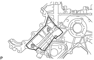
REMOVE TIMING CHAIN COVER SUB-ASSEMBLY
-
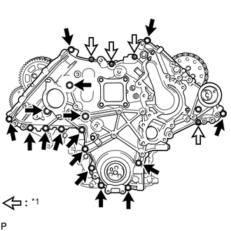
Text in Illustration *1 Nut Remove the 4 nuts and 16 bolts.
-
Using a screwdriver, remove the timing chain cover by prying between the timing chain cover and timing gear case.
Tech Tips
Tape the screwdriver tip before use.
-
Remove the O-ring from the timing gear case.
-
-
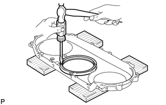
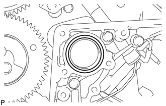
REMOVE FRONT CRANKSHAFT OIL SEAL
-
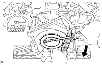
Text in Illustration *1 Wooden Block Place the timing chain cover on wooden blocks.
-
Using a screwdriver and wooden block, pry out the oil seal.
Note
Do not damage the surface of the oil seal press fit hole.
Tech Tips
Tape the screwdriver tip before use.
-
-
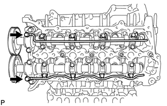
SET NO. 1 CYLINDER TO TDC/COMPRESSION
-
Temporarily install the 2 crankshaft pulley set bolts to the crankshaft.
-
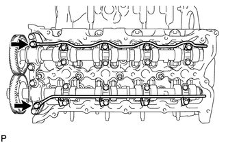
Turn the crankshaft clockwise to set the No. 1 cylinder to TDC.
-
With the crankshaft key 45° counterclockwise from the top position, check that the timing marks of the RH and LH camshaft timing gears are aligned. If not as specified, turn the crankshaft 1 revolution (360°) and align the timing marks as shown below.
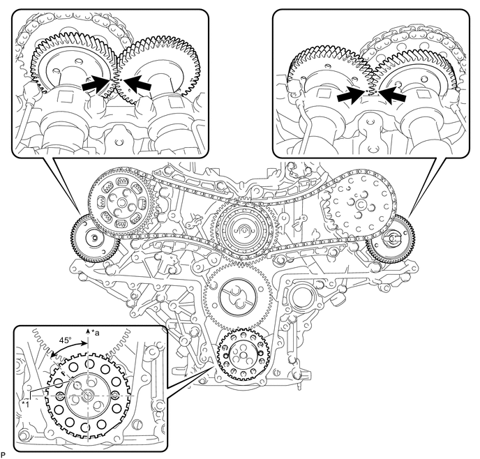
Text in Illustration *1 Key - - *a Top - - -
Remove the 2 crankshaft pulley set bolts.
-
-
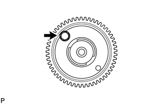
REMOVE NO. 1 CRANKSHAFT POSITION SENSOR PLATE
-
Using a T30 "TORX" wrench, remove the 2 screws and crankshaft position sensor plate.
-
-
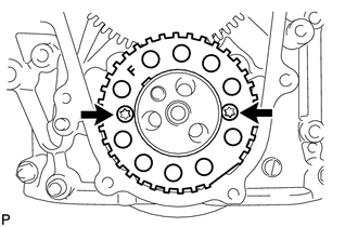
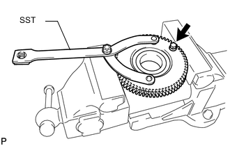
REMOVE PUMP DRIVE SHAFT GEAR
-
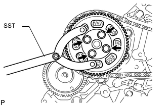
Using SST, hold the pump drive shaft gear.
- SST
- 09960-10010 ( 09962-01000, 09963-01000 )
-
Remove the 4 bolts and pump drive shaft gear.
-
-
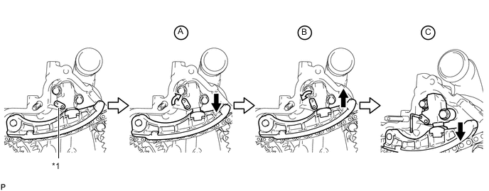
REMOVE NO. 1 CHAIN TENSIONER ASSEMBLY
-
Push the tensioner slipper away from the tensioner, and move the stopper plate clockwise to release the lock as shown in A.
-
Push down the tensioner slipper and move the stopper plate counterclockwise to set the lock as shown in B.
-
Push the tensioner slipper away from the tensioner, and insert a hexagon wrench into the stopper plate hole as shown in C.
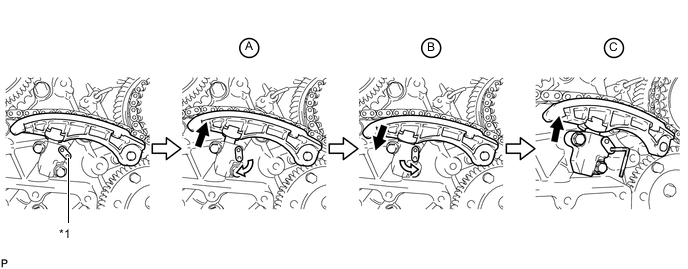
Text in Illustration *1 Stopper Plate - - -
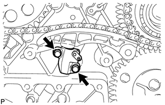
Remove the 2 bolts and No. 1 chain tensioner.
-
-
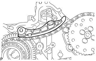
REMOVE NO. 1 CHAIN TENSIONER SLIPPER
-
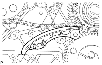
REMOVE NO. 1 CHAIN VIBRATION DAMPER
-
Remove the 2 bolts and No. 1 chain vibration damper.
-
-
REMOVE NO. 1 CAMSHAFT TIMING SPROCKET AND NO. 1 TIMING CHAIN
-
REMOVE NO. 2 CHAIN TENSIONER ASSEMBLY
-
Push the tensioner slipper away from the tensioner, and move the stopper plate clockwise to release the lock as shown in A.
-
Push up the tensioner slipper and move the stopper plate counterclockwise to set the lock as shown in B.
-
Push the tensioner slipper away from the tensioner, and insert a hexagon wrench into the stopper plate hole as shown in C.
Text in Illustration *1 Stopper Plate - - -
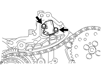
Remove the 2 bolts and No. 2 chain tensioner.
-
-
REMOVE NO. 2 CHAIN TENSIONER SLIPPER
-
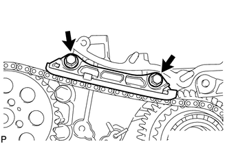
REMOVE NO. 2 CHAIN VIBRATION DAMPER
-
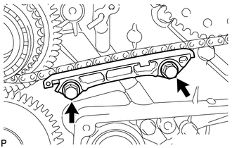
Remove the 2 bolts and No. 2 chain vibration damper.
-
-
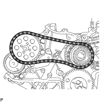
REMOVE NO. 2 CAMSHAFT TIMING SPROCKET AND NO. 2 TIMING CHAIN
-
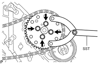
Using SST, hold the No. 2 camshaft timing sprocket.
- SST
- 09960-10010 ( 09962-01000, 09963-01000 )
-
Remove the 4 bolts, No. 2 camshaft timing sprocket and No. 2 timing chain.
-
-
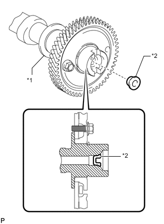
REMOVE FUEL SUPPLY PUMP DRIVE GEAR NUT
-
Using SST, hold the idle gear.
- SST
- 09960-10010 ( 09962-01000, 09963-00700 )
-
Remove the nut.
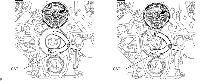
Text in Illustration *A w/ Intercooler *B w/o Intercooler
-
-
REMOVE IDLE GEAR ASSEMBLY
-
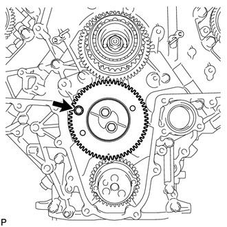
w/ Intercooler:
Using an 8 mm x 1.25 pitch service bolt with a length of 15 mm or more, fix the idle gear in place.
- Torque:
- 13 N*m { 133 kgf*cm, 10 ft.*lbf }
-
Text in Illustration *A w/ Intercooler *B w/o Intercooler Remove the 2 bolts, idle gear thrust plate and idle gear.
-
-
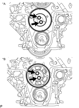
SEPARATE SUB IDLE GEAR, IDLE GEAR SPRING AND IDLE GEAR (w/ Intercooler)
-
Hold the idle gear in a vise between aluminum plates.
Note
Be careful not to damage the gears.
-
Using SST, hole the idle gear, and remove the bolt and sub idle gear.
- SST
- 09960-10010 ( 09962-01000, 09963-00700 )
-
Remove the idle gear spring from the idle gear.
-
-
REMOVE NO. 1 IDLE GEAR SHAFT
-
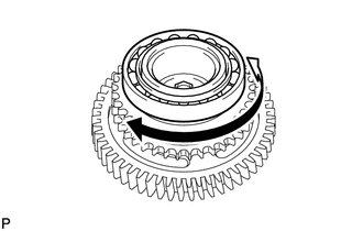
REMOVE FUEL SUPPLY PUMP DRIVE GEAR
-

Using SST, remove the fuel supply pump drive gear.
- SST
- 09950-50013 ( 09951-05010, 09952-05010, 09953-05020, 09954-05031 )
-
-
INSPECT RADIAL BALL BEARING
-
Turn the bearing, and check that the bearing moves smoothly and quietly.
If it moves roughly or noisily, replace the radial ball bearing.
-
-
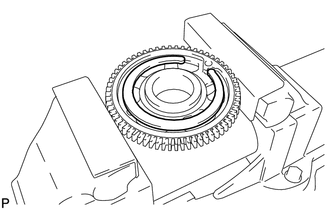
REMOVE RADIAL BALL BEARING
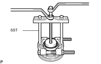
Tech Tips
It is not necessary to remove the bearing unless it is being replaced.
-
Using SST, remove the radial ball bearing.
- SST
- 09950-00020
- 09950-00030
- 09950-60010 ( 09951-00580 )
- 09950-40011 ( 09957-04010 )
-
-
SEPARATE FUEL SUPPLY PUMP DRIVE GEAR AND FUEL SUPPLY PUMP SHAFT SPROCKET
-
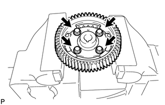
Hold the fuel supply pump shaft sprocket in a vise between aluminum plates.
Note
Be careful not to damage the gears.
-
Remove the 4 bolts and separate the fuel supply pump drive gear and fuel supply pump shaft sprocket.
-
-
REMOVE STRAIGHT PIN
Tech Tips
It is not necessary to remove the straight pin unless it is being replaced.
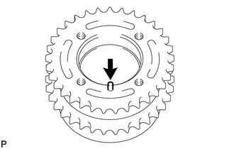
-
Remove the straight pin.
-
-
REMOVE FUEL SUPPLY PUMP ASSEMBLY
-
Using a 6 mm hexagon wrench, remove the hexagon bolt. Then remove the 2 nuts and fuel supply pump.
-
Remove the O-ring.
-
-
REMOVE V-BANK SILENCER
-
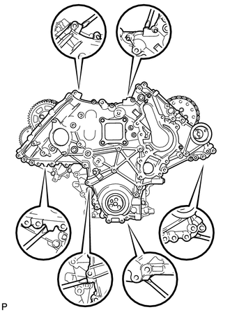
REMOVE TIMING GEAR CASE SUB-ASSEMBLY
-
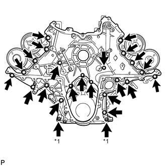
Text in Illustration *1 Nut Remove the 22 bolts, 2 nuts and timing gear case shown in the illustration.
-
Remove the 2 O-rings and timing gear case gasket.
-
-
DISCONNECT NO. 2 VACUUM TRANSMITTING HOSE (w/ Intercooler)
-
DISCONNECT NO. 3 VACUUM TRANSMITTING HOSE (w/ Intercooler)
-
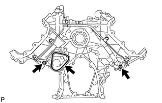
REMOVE NO. 1 VACUUM TRANSMITTING PIPE SUB-ASSEMBLY (w/ Intercooler)
-
Remove the 2 bolts and No. 1 vacuum transmitting pipe.
-
-
REMOVE NO. 2 VACUUM TRANSMITTING PIPE SUB-ASSEMBLY (w/ Intercooler)
-
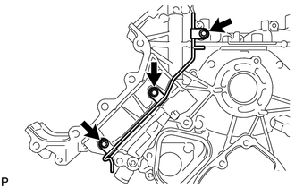
Remove the 3 bolts and No. 2 vacuum transmitting pipe.
-
-
REMOVE NO. 2 TIMING GEAR CASE INSULATOR (w/ Intercooler)
-
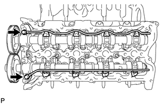
REMOVE NO. 1 AND NO. 2 CAMSHAFTS
-
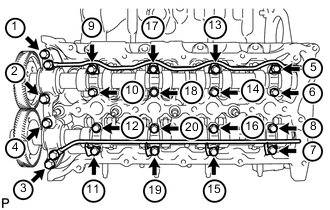
Using a 6 mm x 1.0 pitch service bolt with a length of 16 mm or more, fix the No. 1 camshaft in place.
- Torque:
- 8.0 N*m { 82 kgf*cm, 71 in.*lbf }
-
Loosen the 2 union bolts.
-
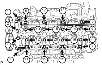
Uniformly loosen and remove the 20 bolts in the sequence shown in the illustration.
-
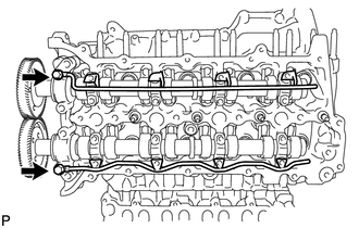
Remove the 2 union bolts and No. 1 and No. 2 oil feed pipes.
-
Remove the 8 No. 3 camshaft bearing caps and No. 1 camshaft bearing cap.
Tech Tips
Be sure to arrange the removed parts for each installation position separately.
-

Remove the No. 1 and No. 2 camshafts.
-
-
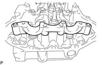
REMOVE NO. 2 CAMSHAFT BEARING CAP
-
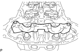
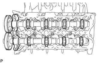
REMOVE NO. 1 VALVE ROCKER ARM
-
Remove the 16 No. 1 valve rocker arms.
Tech Tips
Be sure to arrange the removed parts for each installation position separately.
-
-
REMOVE NO. 1 VALVE LASH ADJUSTER ASSEMBLY
-
Remove the 16 No. 1 valve lash adjusters.
Tech Tips
Be sure to arrange the removed parts for each installation position separately.
-
-
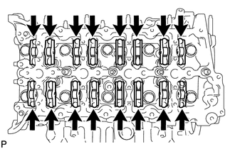
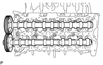
REMOVE CYLINDER HEAD SUB-ASSEMBLY RH
-
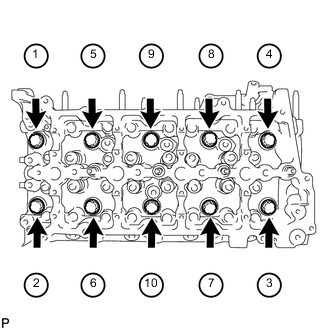
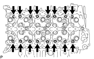
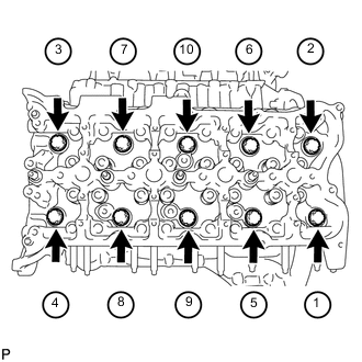
Uniformly loosen and remove the 10 bolts and 10 spacers in the sequence shown in the illustration. Then remove the cylinder head.
Note
-
Be careful not to drop washers into the cylinder head.
-
Head warpage or cracking could result from removing bolts in an incorrect order.
Tech Tips
Be sure to arrange the removed parts for each installation position separately.
-
-
-
REMOVE NO. 1 CYLINDER HEAD GASKET
-
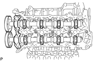
REMOVE NO. 3 AND NO. 4 CAMSHAFTS
-
Using a 6 mm x 1.0 pitch service bolt with a length of 16 mm or more, fix the No. 4 camshaft in place.
- Torque:
- 8.0 N*m { 82 kgf*cm, 71 in.*lbf }
-
Loosen the 2 union bolts.
-
Uniformly loosen and remove the 20 bolts in the sequence shown in the illustration.
-
Remove the 2 union bolts and No. 3 and No. 4 oil feed pipes.
-
Remove the 8 No. 3 camshaft bearing caps and No. 4 camshaft bearing cap.
Tech Tips
Be sure to arrange the removed parts for each installation position separately.
-
Remove the No. 3 and No. 4 camshafts.
-
-
REMOVE NO. 5 CAMSHAFT BEARING CAP
-
REMOVE NO. 2 VALVE ROCKER ARM
-
Remove the 16 No. 2 valve rocker arms.
Tech Tips
Be sure to arrange the removed parts for each installation position separately.
-
-
REMOVE NO. 2 VALVE LASH ADJUSTER ASSEMBLY
-
Remove the 16 No. 2 valve lash adjusters.
Tech Tips
Be sure to arrange the removed parts for each installation position separately.
-
-
REMOVE CYLINDER HEAD SUB-ASSEMBLY LH
-
Uniformly loosen and remove the 10 bolts and 10 spacers in the sequence shown in the illustration. Then remove the cylinder head.
Note
-
Be careful not to drop washers into the cylinder head.
-
Head warpage or cracking could result from removing bolts in an incorrect order.
Tech Tips
Be sure to arrange the removed parts for each installation position separately.
-
-
-
REMOVE NO. 2 CYLINDER HEAD GASKET
-
REPLACE STUD BOLT
Tech Tips
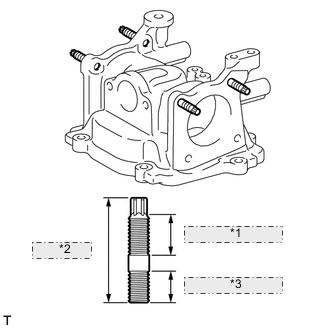
*1 20 mm (0.787 in.) *2 42 mm (1.65 in.) *3 13 mm (0.512 in.) If the stud bolt is deformed or the threads are damaged, replace it.
-
Intake Pipe:
-
Using an E8 "TORX" wrench, replace the 4 stud bolts.
- Torque:
- 6.0 N*m { 61 kgf*cm, 53 in.*lbf }
-
-
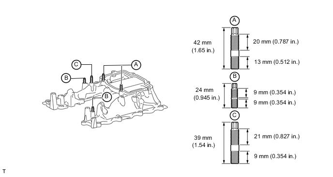
No. 3 Intake Manifold:
-
Using an E8 "TORX" wrench, replace the 2 stud bolts labeled A.
- Torque:
- 6.0 N*m { 61 kgf*cm, 53 in.*lbf }
-
Using an E6 "TORX" wrench, replace the 2 stud bolts labeled B.
- Torque:
- 5.0 N*m { 51 kgf*cm, 44 in.*lbf }
-
Using an E6 "TORX" wrench, replace the stud bolt labeled C.
- Torque:
- 4.0 N*m { 41 kgf*cm, 35 in.*lbf }
-
-
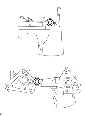
Oil Filter Bracket:
-
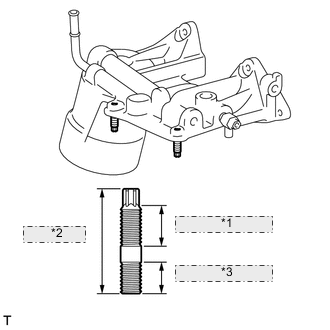
*1 20 mm (0.787 in.) *2 42 mm (1.65 in.) *3 13 mm (0.512 in.) Using an E8 "TORX" wrench, replace the 2 stud bolts.
- Torque:
- 6.0 N*m { 61 kgf*cm, 53 in.*lbf }
-
-
No. 1 Oil Pan:
-
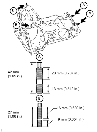
Using an E8 "TORX" wrench, replace the 2 stud bolts labeled A.
- Torque:
- 6.0 N*m { 61 kgf*cm, 53 in.*lbf }
-
Using an E7 "TORX" wrench, replace the 2 stud bolts labeled B.
- Torque:
- 5.2 N*m { 53 kgf*cm, 46 in.*lbf }
-
-
Timing Chain Cover:
-
Using an E7 "TORX" wrench, replace the 2 stud bolts labeled A.
- Torque:
- 6.0 N*m { 61 kgf*cm, 53 in.*lbf }
-
Replace the 2 stud bolts labeled B.
- Torque:
- 12 N*m { 120 kgf*cm, 9 ft.*lbf }
-
-
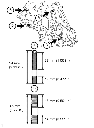
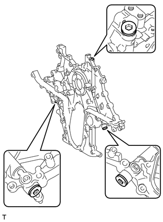
Timing Gear Case:
-
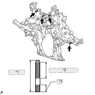
*1 54 mm (2.13 in.) *2 27 mm (1.06 in.) *3 12 mm (0.472 in.) Using an E7 "TORX" wrench, replace the 4 stud bolts.
- Torque:
- 6.0 N*m { 61 kgf*cm, 53 in.*lbf }
-
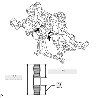
*1 16 mm (0.630 in.) *2 40 mm (1.57 in.) *3 12 mm (0.472 in.) Remove the 2 stud bolts.
-
Remove the adhesive from the threads of the timing gear case.
-
Apply adhesive to 2 or more threads of the 2 stud bolts.
-
Install the 2 stud bolts.
- Torque:
- 10 N*m { 102 kgf*cm, 7 ft.*lbf }
-
-
-
REPLACE STRAIGHT SCREW PLUG
Tech Tips
If water or oil leaks from the straight screw plug or the plug is corroded, replace it.
-
No. 1 Oil Pan:
-
Using a 10 mm hexagon wrench, replace the straight screw plug and/or gasket.
- Torque:
- 50 N*m { 510 kgf*cm, 37 ft.*lbf }
-
Using a 14 mm hexagon wrench, replace the straight screw plug and/or gasket.
- Torque:
- 86 N*m { 877 kgf*cm, 63 ft.*lbf }
-
-
Oil Filter Bracket:
-
Using a 10 mm hexagon wrench, replace the straight screw plug and/or gasket.
- Torque:
- 50 N*m { 510 kgf*cm, 37 ft.*lbf }
-
-
Timing Gear Case:
-
Using a 10 mm hexagon wrench, replace the straight screw plug and/or gasket.
- Torque:
- 40 N*m { 408 kgf*cm, 30 ft.*lbf }
-
-
-
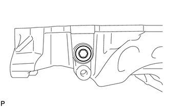
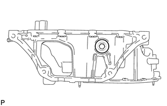
REPLACE CYLINDER BLOCK STRAIGHT SCREW PLUG
Tech Tips
If water leaks from the straight screw plug or the plug is corroded, replace it.
-
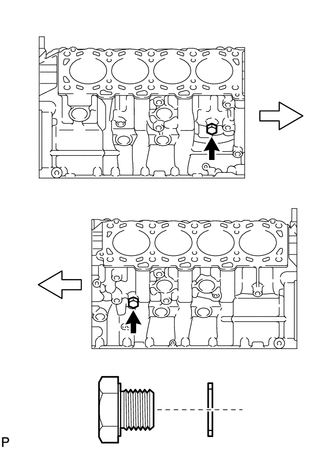
Replace the 2 straight screw plugs and 2 gaskets.
- Torque:
- 38 N*m { 387 kgf*cm, 28 ft.*lbf }
Text in Illustration Front
-
-
REPLACE RING PIN
Tech Tips
It is not necessary to remove the ring pin unless it is being replaced.
-
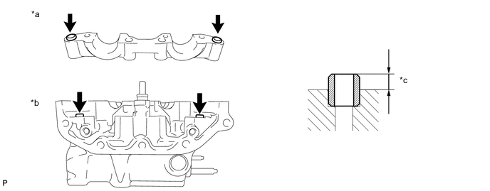
No. 1 and No. 2 Intake Manifold:
-
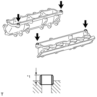
Text in Illustration *a 4.4 to 5.6 mm Replace the ring pin.
Standard protrusion 4.4 to 5.6 mm (0.173 to 0.222 in.)
-
-
Cylinder Head:
-
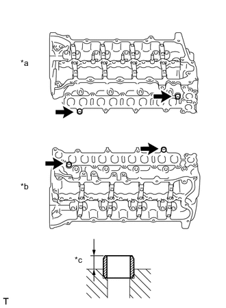
Text in Illustration *a RH *b LH *c 4.4 to 5.6 mm Replace the ring pin.
Standard protrusion 4.4 to 5.6 mm (0.173 to 0.222 in.)
-
-
V-ribbed Belt Tensioner:
-
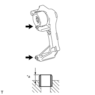
Text in Illustration *a 4.7 to 5.7 mm Replace the ring pin.
Standard protrusion 4.7 to 5.7 mm (0.185 to 0.224 in.)
-
-
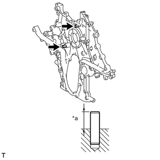
Timing Chain Case:
-
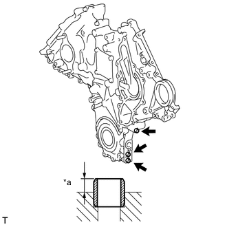
Text in Illustration *a 4.7 to 5.7 mm Replace the ring pin.
Standard protrusion 4.7 to 5.7 mm (0.185 to 0.224 in.)
-
-
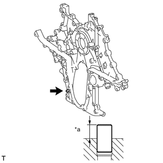
Timing Gear Case:
-
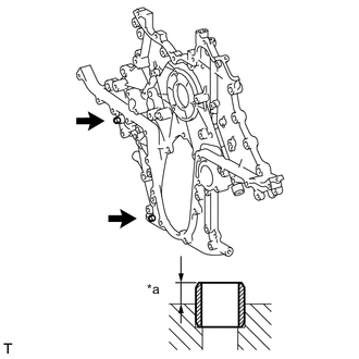
Text in Illustration *a 5.2 to 5.7 mm Replace the ring pin.
Standard protrusion 5.2 to 5.7 mm (0.205 to 0.224 in.)
-
-
Cylinder Head RH:
-
Replace the ring pin.
Standard protrusion 2.5 to 3.5 mm (0.0984 to 0.138 in.) Text in Illustration *a No. 2 Camshaft Bearing Cap *b Cylinder Head RH *c 2.5 to 3.5 mm
-
-
Cylinder Head LH:
-
Replace the ring pin.
Standard protrusion 2.5 to 3.5 mm (0.0984 to 0.138 in.) Text in Illustration *a No. 5 Camshaft Bearing Cap *b Cylinder Head LH *c 2.5 to 3.5 mm
-
-
-
REPLACE CHAIN TENSIONER STRAIGHT PIN
Tech Tips
It is not necessary to remove the straight pin unless it is being replaced.
-
Text in Illustration *a 18 to 20 mm Replace the straight pin.
Standard protrusion 18 to 20 mm (0.709 to 0.787 in.)
-
-
REPLACE TIMING GEAR COVER SET STRAIGHT PIN
Tech Tips
It is not necessary to remove the straight pin unless it is being replaced.
-
Text in Illustration *a 5.0 to 7.5 mm Replace the straight pin.
Standard protrusion 5.0 to 7.5 mm (0.197 to 0.295 in.)
-
-
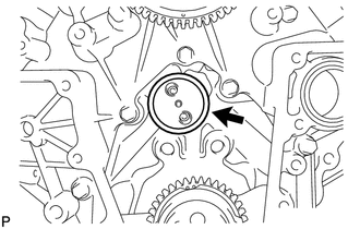
REPLACE HOLE PLUG (w/o Intercooler)
Tech Tips
It is not necessary to remove a hole plug unless it is being replaced.
-
Remove the hole plug from the No. 4 camshaft.
-
Text in Illustration *1 No. 4 Camshaft *2 Hole Plug Using a 12 mm steel bar and hammer, tap in the hole plug as shown in the illustration.
-
-
REPLACE TIGHT PLUG (w/o Intercooler)
Note
If oil leaks from a tight plug or a plug is corroded, replace it.
-
Remove the tight plug from the timing chain cover.
-
Apply adhesive to a new tight plug.
Adhesive Toyota Genuine Adhesive 1324, Three Bond 1324 or equivalent -
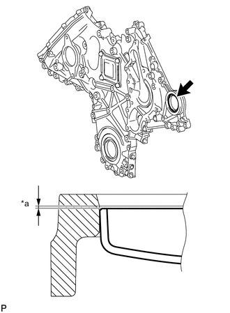
Text in Illustration *a 0.2 to 0.5 mm Using SST and a hammer, tap in the tight plug as shown in the illustration.
- SST
- 09950-60010 ( 09951-00550 )
- 09950-70010 ( 09951-07100 )
Standard depth 0.2 to 0.5 mm (0.00787 to 0.0197 in.)
-