ENGINE UNIT INSPECTION

PROCEDURE
-
INSPECT CYLINDER HEAD SET BOLT
-
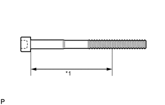
Text in Illustration *1 Measuring Point Using a vernier caliper, measure the diameter of the elongated thread at the measuring point.
Measuring point 94 mm (3.70 in.) for intake side bolt 89 mm (3.50 in.) for exhaust side bolt Standard diameter 10.85 to 11.00 mm (0.427 to 0.433 in.) Minimum diameter 10.6 mm (0.417 in.) If the diameter is less than the minimum, replace the cylinder head bolt.
Tech Tips
If a visual check reveals no excessively thin areas, check the center of the bolt (see illustration) and find the area that has the smallest diameter.
-
-
INSPECT NO. 1 VALVE ROCKER ARM SUB-ASSEMBLY
-
Turn the roller by hand to check that it turns smoothly.
If the roller does not turn smoothly, replace the valve rocker arm.
-
-
INSPECT VALVE LASH ADJUSTER ASSEMBLY
Note
-
Keep the adjuster free from dirt and foreign objects.
-
Use only clean engine oil.
-
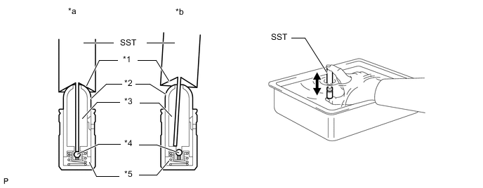
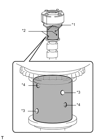
Place the lash adjuster into a container full of new engine oil.
-
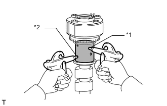
Insert the tip of SST into the lash adjuster plunger and use the tip to press down on the check ball inside the plunger.
- SST
- 09276-75010
-
Squeeze SST and the lash adjuster together to move the plunger up and down 5 to 6 times.
-
Check the movement of the plunger and bleed air.
OK Plunger moves up and down. Text in Illustration *1 Taper Part *2 Plunger *3 Low Pressure Chamber *4 Check Ball *5 High Pressure Chamber *a CORRECT *b INCORRECT Note
When bleeding high-pressure air from the compression chamber, make sure that the tip of SST is actually pressing the check ball as shown in the illustration. If the check ball is not pressed, air will not bleed.
-
After bleeding the air, remove SST. Then try to quickly and firmly press the plunger with your fingers.
OK Plunger can be pressed 3 times. If the plunger can still be compressed after pressing it 3 times, replace the valve lash adjuster with a new one.
-
-
INSPECT CAMSHAFT SUB-ASSEMBLY
-
Inspect the camshaft for runout.
-
Place the camshaft on V-blocks.
-
Using a dial indicator, measure the circle runout at the center journal.
Maximum circle runout 0.04 mm (0.00157 in.) If the circle runout is more than the maximum, replace the camshaft sub-assembly.
Tech Tips
Check the oil clearance after replacing the camshaft.
-
-
Using a micrometer, measure the cam lobe height.
Standard Cam Lobe Height Item Specified Condition Intake 44.291 to 44.441 mm (1.744 to 1.750 in.) Exhaust 44.196 to 44.346 mm (1.740 to 1.746 in.) Minimum Cam Lobe Height Item Specified Condition Intake 44.241 mm (1.742 in.) Exhaust 44.146 mm (1.738 in.) If the cam lobe height is less than the minimum, replace the camshaft sub-assembly.
-
Using a micrometer, measure the journal diameter.
Standard Journal Diameter Item Specified Condition No. 1 journal 29.956 to 29.970 mm (1.179 to 1.180 in.) Other journals 25.959 to 25.975 mm (1.022 to 1.023 in.) If the journal diameter is not as specified, check the oil clearance.
-
-
INSPECT CAMSHAFT OIL CLEARANCE
-
Clean the bearing caps, camshaft housing and camshaft journals.
-
Place the camshafts on the camshaft housing.
-
Text in Illustration *1 Plastigage Lay a strip of Plastigage across each of the camshaft journals.
-
Install the camshaft bearing caps Click here.
Note
Do not turn the camshaft.
-
Install the camshaft housing Click here.
Note
Do not turn the camshaft.
-
Remove the camshaft bearing caps Click here.
-
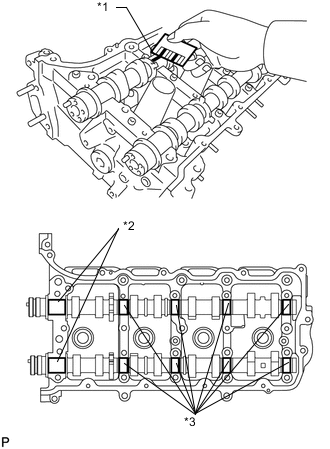
Text in Illustration *1 Plastigage *2 No. 1 Journal *3 Other Journals Measure the Plastigage at its widest point.
Standard Oil Clearance Item Specified Condition No. 1 journal 0.030 to 0.065 mm (0.00118 to 0.00256 in.) Other journals 0.025 to 0.062 mm (0.000984 to 0.00244 in.) Maximum Oil Clearance Item Specified Condition No. 1 journal 0.10 mm (0.00394 in.) Other journals 0.09 mm (0.00354 in.) If the oil clearance is more than the maximum, replace the camshaft. If necessary, replace the camshaft housing.
-
-
INSPECT CAMSHAFT TIMING GEAR
-
Install the camshaft bearing caps Click here.
Tech Tips
Only install the intake camshaft.
-
Install the camshaft housing Click here.
-
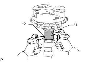
Apply a light coat of engine oil to the camshaft and camshaft timing gear.
-
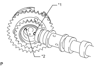
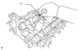
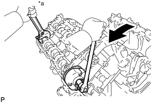
Using the hexagonal portion of the camshaft, align and attach the knock pin of the camshaft with the pin hole of the camshaft timing gear.
Text in Illustration *1 Knock Pin *2 Key Groove Note
-
Do not forcefully push on the camshaft timing gear. This may cause the camshaft knock pin tip to damage the installation surface of the camshaft timing gear.
-
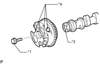
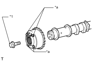
Do not loosen or remove the 3 bolts shown in the illustration. If any of them are loosened or removed, the backlash of the gear in the timing tube will go out of adjustment. In this case, replace the camshaft timing gear assembly with a new one.
Text in Illustration *1 Flange Bolt *2 Knock Pin *a Do not remove -
-
Apply a light coat of engine oil to the threads and under the head of the bolt.
-
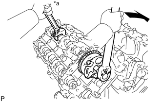
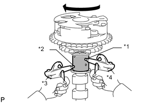
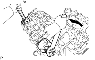
Text in Illustration *a Hold 
Turn Using a wrench to hold the hexagonal portion of the camshaft, install the camshaft timing gear with the bolt.
- Torque:
- 100 N*m { 1020 kgf*cm, 74 ft.*lbf }
-
Remove the camshaft bearing caps Click here.
-
Check the lock of the camshaft timing gear.
-
Make sure that the camshaft timing gear is locked.
Note
Be careful not to damage the camshaft.
-
-
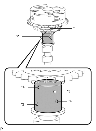
Text in Illustration *1 Advance Side Path *2 Retard Side Path *3 Open *4 Close 
Vinyl Tape Release the lock pin.
-
Cover the 4 oil paths of the cam journal with vinyl tape as shown in the illustration.
-
Break through the tape of the advance side path and retard side path as shown in the illustration.
-
Text in Illustration *1 Advance Side Path *2 Retard Side Path Apply approximately 200 kPa (2.0 kgf/cm2, 29 psi) of air pressure to the two broken paths.
Note
Cover the paths with a piece of cloth when applying pressure to keep oil from splashing.
-
Text in Illustration *1 Advance Side Path *2 Retard Side Path *3 Decompress *4 Hold Pressure Check that the camshaft timing gear revolves in the advance direction when reducing the air pressure applied to the retard side path.
Tech Tips
This operation releases the lock pin for the most retarded position.
-
When the camshaft timing gear reaches the most advanced position, release the air pressure from the retard side path and advance side path, in that order.
Note
Do not release the air pressure from the advance side path first. The gear may abruptly shift in the retard direction and break the lock pin.
-
-
Check for smooth rotation.
-
Turn the camshaft timing gear within its movable range (21°) 2 or 3 times, but do not turn it to the most retarded position. Make sure that the gear turns smoothly.
Note
Do not use air pressure to perform the smooth rotation check.
-
-
Check the lock in the most retarded position.
-
Confirm that the camshaft timing gear is locked at the most retarded position.
-
-
Install the camshaft bearing caps Click here.
Tech Tips
Only install the intake camshaft.
-
Install the camshaft housing Click here.
-
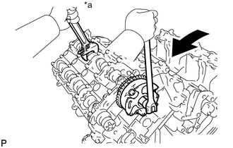
Text in Illustration *a Hold Turn Hold the hexagonal portion of the camshaft with a wrench and loosen the bolt.
-
Remove the camshaft bearing caps Click here.
-

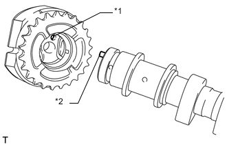
Text in Illustration *1 Flange Bolt *2 Knock Pin *a Do not remove Remove the flange bolt and camshaft timing gear.
-
-
INSPECT CAMSHAFT TIMING EXHAUST GEAR
-
Install the camshaft bearing caps Click here.
Tech Tips
Only install the exhaust camshaft.
-
Install the camshaft housing Click here.
-
Apply a light coat of engine oil to the camshaft and camshaft timing exhaust gear.
-
Using the hexagonal portion of the camshaft, align and attach the knock pin of the camshaft with the pin hole of the camshaft timing exhaust gear.
Text in Illustration *1 Key Groove *2 Knock Pin Note
-
Do not forcefully push on the camshaft timing exhaust gear. This may cause the camshaft knock pin tip to damage the installation surface of the camshaft timing exhaust gear.
-
Do not loosen or remove the 4 bolts shown in the illustration. If any of them are loosened or removed, the backlash of the gear in the timing tube will go out of adjustment. In this case, replace the camshaft timing exhaust gear assembly with a new one.
Text in Illustration *1 Flange Bolt *a Do not remove -
-
Apply a light coat of engine oil to the threads and under the head of the bolt.
-
Text in Illustration *a Hold Turn Using a wrench to hold the hexagonal portion of the camshaft, install the camshaft timing exhaust gear with the bolt.
- Torque:
- 100 N*m { 1020 kgf*cm, 74 ft.*lbf }
-
Remove the camshaft bearing caps Click here.
-
Check the camshaft timing exhaust gear lock.
-
Make sure that the camshaft timing exhaust gear is locked.
-
-
Text in Illustration *1 Advance Side Path *2 Retard Side Path *3 Open *4 Close Vinyl Tape Release the lock pin.
-
Cover the 4 oil paths of the cam journal with vinyl tape as shown in the illustration.
-
Break through the tape of the advance side path and retard side path as shown in the illustration.
-
Text in Illustration *1 Advance Side Path *2 Retard Side Path Apply approximately 200 kPa (2.0 kgf/cm2, 29 psi) of air pressure to the two broken paths (the advance side path and the retard side path).
Note
Cover the paths with a piece of cloth when applying pressure to keep oil from splashing.
-
Text in Illustration *1 Advance Side Path *2 Retard Side Path *3 Decompress *4 Hold Pressure Check that the camshaft timing exhaust gear turns in the retard direction when reducing the air pressure applied to the advance side path.
Tech Tips
The lock pin is released and the camshaft timing exhaust gear turns in the retard direction.
-
When the camshaft timing exhaust gear moves to the most retarded position, release the air pressure from the advance side path, and then release the air pressure from the retard side path.
Note
Be sure to release the air pressure from the advance side path first. If the air pressure of the retard side path is released first, the camshaft timing exhaust gear may abruptly shift in the advance direction and break the lock pin or other parts.
-
-
Check for smooth rotation.
-
Turn the camshaft timing exhaust gear within its movable range (18.5°) 2 or 3 times, but do not turn it to the most advanced position. Make sure that the gear turns smoothly.
Note
When the air pressure is released from the advance side path and then from the retard side path, the gear automatically returns to the most advanced position due to the advance assist spring operation, and locks. Gradually release the air pressure from the retard side path before performing the smooth rotation check.
-
-
Check the lock at the most advanced position.
-
Make sure that the camshaft timing exhaust gear is locked at the most advanced position.
-
-
Install the camshaft bearing caps Click here.
Tech Tips
Only install the exhaust camshaft.
-
Install the camshaft housing Click here.
-
Text in Illustration *a Hold Turn Hold the hexagonal portion of the camshaft with a wrench and loosen the bolt.
-
Remove the camshaft bearing caps Click here.
-

Text in Illustration *1 Flange Bolt *a Do not remove Remove the flange bolt and camshaft timing exhaust gear.
-
-
INSPECT NO. 1 CHAIN SUB-ASSEMBLY
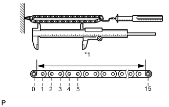
Text in Illustration *1 Measuring Area
-
Using a spring scale, pull the chain with a force of 147 N (15 kgf, 33.0 lbf) as shown in the illustration.
-
Using a vernier caliper, measure the length of 15 pins.
Maximum chain elongation 136.9 mm (5.39 in.) Tech Tips
Perform the measurement at 3 random places.
If the elongation is more than the maximum, replace the No. 1 chain.
-
-
INSPECT NO. 2 CHAIN SUB-ASSEMBLY
-
Using a spring scale, pull the chain with a force of 147 N (15 kgf, 33.0 lbf) as shown in the illustration.
-
Using a vernier caliper, measure the length of 15 pins.
Maximum chain elongation 137.6 mm (5.42 in.) Tech Tips
Perform the measurement at 3 random places.
If the elongation is more than the maximum, replace the No. 2 chain.
-
-
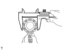
INSPECT CRANKSHAFT TIMING SPROCKET RH
-
Wrap the chain around the sprocket.
-
Using a vernier caliper, measure the sprocket diameter with the chain.
Minimum sprocket diameter (with chain) 61.4 mm (2.42 in.) If the diameter is less than the minimum, replace the chain and crankshaft timing sprocket RH.
Tech Tips
The vernier caliper must contact the chain rollers for the measurement.
-
-
INSPECT CRANKSHAFT TIMING SPROCKET LH
-
Wrap the chain around the sprocket.
-
Using a vernier caliper, measure the sprocket diameter with the chain.
Minimum sprocket diameter (with chain) 61.4 mm (2.42 in.) If the diameter is less than the minimum, replace the chain and crankshaft timing sprocket LH.
Tech Tips
The vernier caliper must contact the chain rollers for the measurement.
-
-
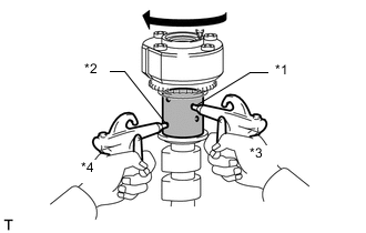
INSPECT NO. 1 CHAIN TENSIONER ASSEMBLY
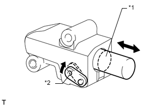
Text in Illustration *1 Plunger *2 Stopper Plate
-
Move the stopper plate clockwise to release the lock. Push the plunger and check that it moves smoothly.
If necessary, replace the No. 1 chain tensioner.
-
-
INSPECT NO. 2 CHAIN TENSIONER ASSEMBLY
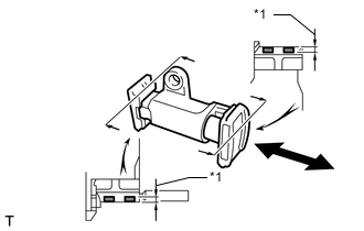
Text in Illustration *1 Depth
-
Check that the plunger moves smoothly.
-
Measure the worn depth of the chain tensioner.
Maximum depth 0.9 mm (0.0354 in.) If the depth is more than the maximum, replace the No. 2 chain tensioner.
-
-
INSPECT NO. 3 CHAIN TENSIONER ASSEMBLY
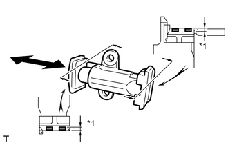
Text in Illustration *1 Depth
-
Check that the plunger moves smoothly.
-
Measure the worn depth of the chain tensioner.
Maximum depth 0.9 mm (0.0354 in.) If the depth is more than the maximum, replace the No. 3 chain tensioner.
-
-
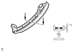
INSPECT NO. 1 CHAIN TENSIONER SLIPPER
-
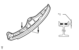
Text in Illustration *1 Depth for LH:
Measure the worn depth of the chain tensioner slipper.
Maximum depth 1.0 mm (0.0394 in.) If the depth is more than the maximum, replace the No. 1 chain tensioner slipper.
-
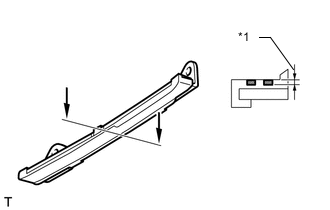
Text in Illustration *1 Depth for RH:
Measure the worn depth of the chain tensioner slipper.
Maximum depth 1.0 mm (0.0394 in.) If the depth is more than the maximum, replace the No. 1 chain tensioner slipper.
-
-
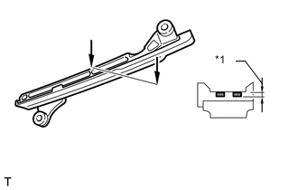
INSPECT NO. 1 CHAIN VIBRATION DAMPER
-
Text in Illustration *1 Depth for LH:
Measure the worn depth of the chain vibration damper.
Maximum depth 1.0 mm (0.0394 in.) If the depth is more than the maximum, replace the No. 1 chain vibration damper.
-
Text in Illustration *1 Depth for RH:
Measure the worn depth of the chain vibration damper.
Maximum depth 1.0 mm (0.0394 in.) If the depth is more than the maximum, replace the No. 1 chain vibration damper.
-
-
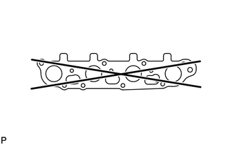
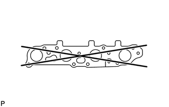
INSPECT EXHAUST MANIFOLD SUB-ASSEMBLY LH
-
Using a precision straightedge and feeler gauge, measure the warpage of the surface where the exhaust manifold LH contacts the cylinder head.
Maximum warpage 0.7 mm (0.0276 in.) If the warpage is more than the maximum, replace the exhaust manifold LH.
-
-
INSPECT EXHAUST MANIFOLD SUB-ASSEMBLY RH
-
Using a precision straightedge and feeler gauge, measure the warpage of the surface where the exhaust manifold RH contacts the cylinder head.
Maximum warpage 0.7 mm (0.0276 in.) If the warpage is more than the maximum, replace the exhaust manifold RH.
-