DRIVE BELT INSTALLATION
PROCEDURE
-
INSTALL V-RIBBED BELT
-
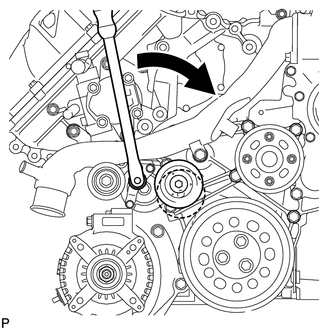
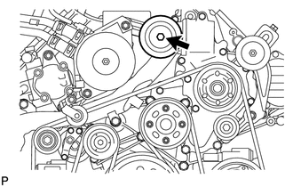
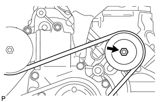
Attach a wrench to the V-ribbed belt tensioner bracket and turn the wrench clockwise.
-
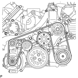
Install the V-ribbed belt as shown in the illustration.
-
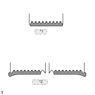
*1 CORRECT *2 INCORRECT Check that the belt fits properly in the ribbed grooves.
Tech Tips
Check with your hand to confirm that the belt has not slipped out of the groove on the bottom of the pulley.
If it has slipped out, replace the V-ribbed belt. Install a new V-ribbed belt.
-
-
INSTALL NO. 3 IDLER PULLEY (w/ Viscous Heater)
-
Align the No. 3 idler pulley bracket knock pin and No. 1 idler pulley bracket knock pin hole and install the No. 3 idler pulley with the nut.
- Torque:
- 88 N*m { 898 kgf*cm, 64 ft.*lbf }
-
-
INSTALL NO. 1 IDLER PULLEY (w/ Viscous Heater)
-
Install the collar, No. 1 idler pulley and cover with the bolt.
- Torque:
- 49 N*m { 495 kgf*cm, 36 ft.*lbf }
-
-
INSTALL V-RIBBED BELT (w/ Viscous Heater)
-
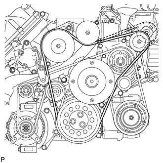
Install the V-ribbed belt as shown in the illustration.
-
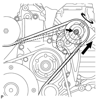
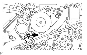
Temporarily install the lock nut, and turn the bolt clockwise.
-
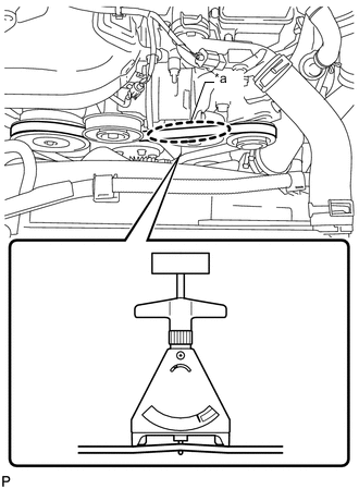
Text in Illustration *a Measuring Point Using a belt tension gauge, inspect the belt tension.
Standard Belt Tension Item Condition Specified Condition New belt 5 to 35°C (41 to 95°F) 550 to 800 N (56 to 82 kgf, 123.6 to 179.8 lbf) Used belt 5 to 35°C (41 to 95°F) 300 to 500 N (31 to 51 kgf, 67.4 to 112.4 lbf) Tech Tips
-
When measuring the tension of a new belt, measure the tension immediately after installing it to the engine but before starting the engine.
-
A "new belt" is a belt which has been used for less than 5 minutes on a running engine.
-
A "used belt" is a belt which has been used on a running engine for 5 minutes or more.
-
After installing a new belt, run the engine for approximately 5 minutes and then recheck the tension.
-
-
Tighten the nut.
- Torque:
- 40 N*m { 408 kgf*cm, 30 ft.*lbf }
-
*1 CORRECT *2 INCORRECT Check that the belt fits properly in the ribbed grooves.
Tech Tips
Check with your hand to confirm that the belt has not slipped out of the groove on the bottom of the pulley.
If it has slipped out, replace the V-ribbed belt. Install a new V-ribbed belt.
-
-
INSTALL INTAKE AIR CONNECTOR
-
TEMPORARILY INSTALL NO. 1 AIR CLEANER HOSE
-
INSTALL AIR CLEANER CAP SUB-ASSEMBLY
-
INSTALL NO. 1 ENGINE COVER SUB-ASSEMBLY (w/ Intercooler)
-
INSTALL UPPER RADIATOR SUPPORT SEAL
-
INSTALL NO. 1 ENGINE UNDER COVER SUB-ASSEMBLY
-
INSTALL FRONT FENDER SPLASH SHIELD SUB-ASSEMBLY RH
-
INSTALL FRONT FENDER SPLASH SHIELD SUB-ASSEMBLY LH