PROCEDURE
- Click here
REMOVE OIL FILTER ELEMENT
- Click here
REMOVE OIL PRESSURE SENDER GAUGE ASSEMBLY
- Click here
REMOVE OIL FILTER BRACKET SUB-ASSEMBLY
- Click here
REMOVE CRANKSHAFT PULLEY
- Click here
REMOVE OIL FILLER CAP SUB-ASSEMBLY
-
Remove the oil filler cap.
-
Remove the gasket from the oil filler cap.
-
- Click here
REMOVE OIL FILLER CAP HOUSING
-
Remove the 2 bolts, oil filler cap housing and gasket.
-
- Click here
REMOVE SPARK PLUG
- Click here
REMOVE KNOCK SENSOR
- Click here
REMOVE VVT SENSOR
- Click here
REMOVE CAMSHAFT POSITION SENSOR
- Click here
REMOVE CRANKSHAFT POSITION SENSOR PROTECTOR
- Click here
REMOVE CRANKSHAFT POSITION SENSOR
- Click here
REMOVE CAMSHAFT TIMING OIL CONTROL VALVE ASSEMBLY
-
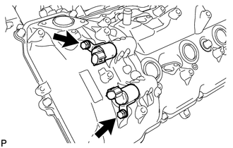
for Bank 1:
Remove the 2 bolts and 2 camshaft oil control valves.
-
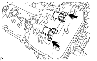
for Bank 2:
Remove the 2 bolts and 2 camshaft oil control valves.
-
- Click here
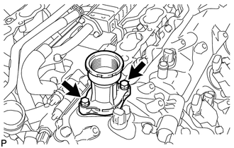
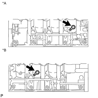
REMOVE CYLINDER BLOCK WATER DRAIN COCK SUB-ASSEMBLY
-
Remove the 2 water drain cock plugs from the cylinder block water drain cocks.
Table 1. Text in Illustration *A for LH Side *B for RH Side -
Remove the 2 cylinder block water drain cocks from the cylinder block.
-
- Click here
REMOVE WATER INLET HOUSING
- Click here
REMOVE FRONT WATER BY-PASS JOINT
- Click here
REMOVE CYLINDER HEAD COVER SUB-ASSEMBLY LH
- Click here
REMOVE CYLINDER HEAD COVER SUB-ASSEMBLY RH
- Click here
REMOVE OIL CONTROL VALVE FILTER
-
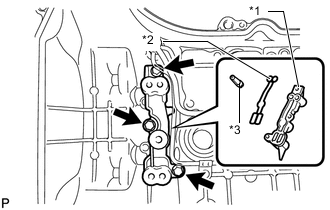
for Bank 1:
Remove the 3 bolts, cylinder head cover spacer, gasket and oil control valve filter.
Table 2. Text in Illustration *1 Cylinder Head Cover Spacer *2 Gasket *3 Oil Control Valve Filter -
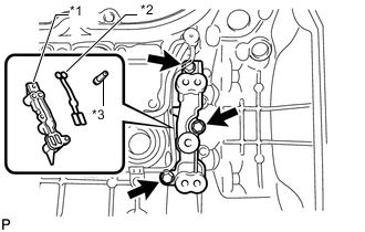
for Bank 2:
Remove the 3 bolts, cylinder head cover spacer, gasket and oil control valve filter.
Table 3. Text in Illustration *1 Cylinder Head Cover Spacer *2 Gasket *3 Oil Control Valve Filter
-
- Click here
REMOVE SPARK PLUG TUBE GASKET
-
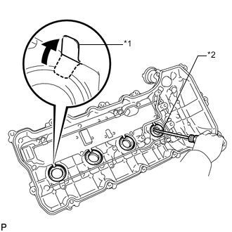
Bend the 4 ventilation baffle plate claws on the cylinder head cover to an angle of 90° or more.
Table 4. Text in Illustration *1 Ventilation Baffle Plate Claw *2 Protective Tape -
Using a screwdriver, pry out the gaskets.
Note:Be careful not to damage the cylinder head cover.
Tip:
-
Be careful not to damage the gasket when removing it as the removed gasket needs to be used when installing a new one.
-
Tape the screwdriver tip before use.
-
-
- Click here
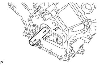
REMOVE ENGINE OIL LEVEL SENSOR
- Click here
REMOVE V-RIBBED BELT TENSIONER ASSEMBLY
- Click here
REMOVE TIMING CHAIN COVER SUB-ASSEMBLY
- Click here
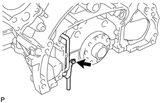
REMOVE ENGINE WATER PUMP ASSEMBLY
- Click here
REMOVE WATER INLET PIPE
- Click here
REMOVE FRONT CRANKSHAFT OIL SEAL
-
Place the timing chain cover on wooden blocks.
-
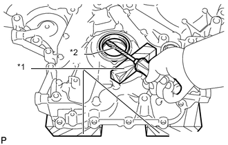
Place the oil pump on a wooden block.
Table 5. Text in Illustration *1 Wooden Block *2 Protective Tape -
Using a screwdriver and wooden block, pry out the front crankshaft oil seal.
Note:Do not damage the surface of the front crankshaft oil seal press fit hole.
Tip:Tape the screwdriver tip before use.
-
- Click here
SET NO. 1 CYLINDER TO TDC/COMPRESSION
-
Temporarily install the pulley set bolt.
-
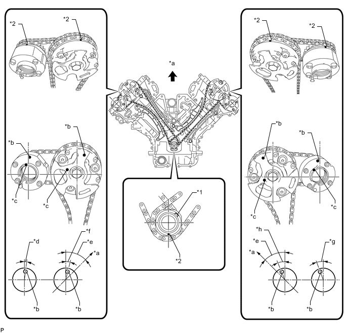
Rotate the crankshaft clockwise so that the timing marks on the crankshaft timing gear and camshaft timing gears are as shown in the illustration.
Tip:If the timing marks do not align, rotate the crankshaft clockwise again and align the timing marks.
Table 6. Text in Illustration *1 Crankshaft Timing Gear Key *2 Timing Mark *a Toward Ceiling *b Timing Mark Position *c Knock Pin Position *d Approximately 2° *e Approximately 45° *f Approximately 16° *g Approximately 18° *h Approximately 32°
-
- Click here
REMOVE NO. 1 CHAIN TENSIONER ASSEMBLY LH
- Click here
REMOVE CHAIN TENSIONER SLIPPER LH
- Click here
REMOVE NO. 1 CHAIN VIBRATION DAMPER LH
- Click here
REMOVE NO. 1 CHAIN SUB-ASSEMBLY LH
- Click here
REMOVE NO. 3 CHAIN TENSIONER ASSEMBLY
- Click here
REMOVE NO. 1 CHAIN TENSIONER ASSEMBLY RH
- Click here
REMOVE CHAIN TENSIONER SLIPPER RH
- Click here
REMOVE NO. 1 CHAIN VIBRATION DAMPER RH
- Click here
REMOVE NO. 1 CHAIN SUB-ASSEMBLY RH
- Click here
REMOVE NO. 2 CHAIN TENSIONER ASSEMBLY
- Click here
REMOVE CRANKSHAFT TIMING GEAR KEY
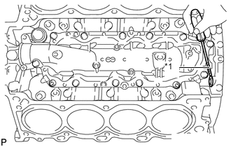
-
Using a screwdriver, remove the 2 crankshaft timing gear keys from the crankshaft.
-
- Click here
REMOVE CAMSHAFT BEARING CAP LH
- Click here
REMOVE NO. 3 CAMSHAFT SUB-ASSEMBLY
- Click here
REMOVE NO. 4 CAMSHAFT SUB-ASSEMBLY
- Click here
REMOVE CAMSHAFT HOUSING SUB-ASSEMBLY LH
- Click here
REMOVE CAMSHAFT BEARING CAP RH
- Click here
REMOVE NO. 1 CAMSHAFT SUB-ASSEMBLY
- Click here
REMOVE NO. 2 CAMSHAFT SUB-ASSEMBLY
- Click here
REMOVE CAMSHAFT HOUSING SUB-ASSEMBLY RH
- Click here
REMOVE NO. 1 VALVE ROCKER ARM SUB-ASSEMBLY
- Click here
REMOVE VALVE LASH ADJUSTER ASSEMBLY
- Click here
REMOVE VALVE STEM CAP
- Click here
REMOVE CYLINDER HEAD SUB-ASSEMBLY LH
- Click here
REMOVE NO. 2 CYLINDER HEAD GASKET
- Click here
REMOVE CYLINDER HEAD SUB-ASSEMBLY
- Click here
REMOVE CYLINDER HEAD GASKET
- Click here
REMOVE CYLINDER BLOCK WATER JACKET SPACER
-
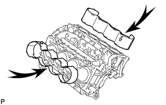
Remove the 2 cylinder block water jacket spacers from the cylinder block.
Note:Be sure to remove the cylinder block water jacket spacers. Otherwise, they may fall and become damaged when the cylinder block is inverted.
-
- Click here
REMOVE OIL RETURN PIPE GASKET
-
Using a screwdriver, pry out the oil return pipe gasket.
Table 7. Text in Illustration *1 Protective Tape Tip:Tape the screwdriver tip before use.
-
- Click here
REMOVE VENTILATION PIPE GASKET
-
Using a screwdriver, pry out the ventilation pipe gasket.
Table 8. Text in Illustration *1 Protective Tape Tip:Tape the screwdriver tip before use.
-
- Click here
REMOVE NO. 1 HEAT EXCHANGER COVER
-
Remove the 12 bolts and 2 nuts.
Table 9. Text in Illustration 
Bolt 
Nut -
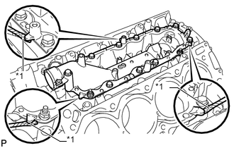
Remove the No. 1 heat exchanger cover by prying between the No. 1 heat exchanger cover and cylinder block with a screwdriver.
Table 10. Text in Illustration *1 Protective Tape Tip:Tape the screwdriver tip before use.
-
- Click here
REMOVE NO. 2 OIL PAN SUB-ASSEMBLY
-
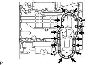
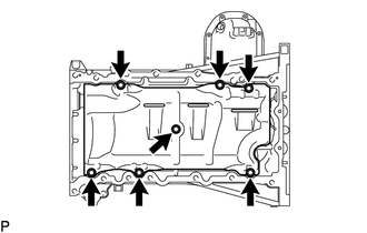
Remove the 14 bolts and 2 nuts.
Table 11. Text in Illustration Bolt Nut -
Insert the blade of an oil pan seal cutter between the oil pans. Cut through the applied sealer and remove the No. 2 oil pan.
Note:Be careful not to damage the contact surfaces of the oil pans.
-
- Click here
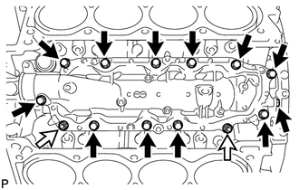
REMOVE NO. 1 OIL PAN SUB-ASSEMBLY
-
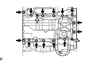
Remove the 14 bolts and 2 nuts.
Table 12. Text in Illustration Bolt Nut Tip:Be sure to clean the bolts and stud bolts and check the threads for cracks or other damage.
-
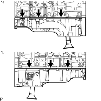
Remove the No. 1 oil pan by prying between the No. 1 oil pan and cylinder block with a screwdriver.
Table 13. Text in Illustration *a for LH Side *b for RH Side Note:Be careful not to damage the contact surfaces of the cylinder block and No. 1 oil pan.
Tip:Tape the screwdriver tip before use.
-
- Click here
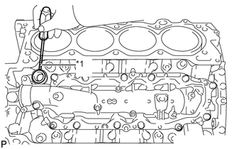
REMOVE NO. 1 OIL PAN BAFFLE PLATE
-
Remove the 7 bolts and No. 1 oil pan baffle plate.
-
- Click here
REMOVE OIL STRAINER SUB-ASSEMBLY
-
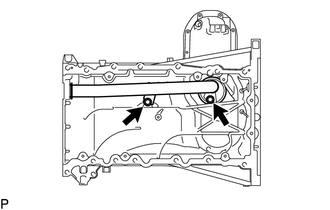
Remove the 2 bolts, oil strainer and O-ring.
-
- Click here
REMOVE REAR ENGINE OIL SEAL RETAINER
-
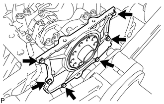
Remove the 6 bolts and rear engine oil seal retainer.
-
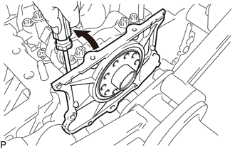
Using a screwdriver, pry out the rear engine oil seal retainer.
Tip:Tape the screwdriver tip before use.
-
- Click here
REMOVE REAR CRANKSHAFT OIL SEAL
-
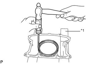
Place the rear engine oil seal retainer on wooden blocks.
Table 14. Text in Illustration *1 Wooden Block -
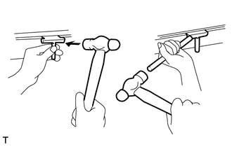
Using a screwdriver and hammer, tap out the rear crankshaft oil seal.
-
- Click here
REMOVE OIL DRAIN PIPE SUB-ASSEMBLY
-
Remove the bolt and oil drain pipe.
-
Remove the O-ring.
-
- Click here
REMOVE RING PIN
Note:It is not necessary to remove a ring pin unless it is being replaced.
- Click here
REMOVE STUD BOLT
Note:If a stud bolt is deformed or its threads are damaged, replace it.