CAMSHAFT INSTALLATION
PROCEDURE
-
INSTALL CAMSHAFT BEARING CAP LH
-
Apply a light coat of engine oil to the camshaft journals, camshaft housing and camshaft bearing caps.
-
Install the No. 3 and No. 4 camshafts to the camshaft housing.
-
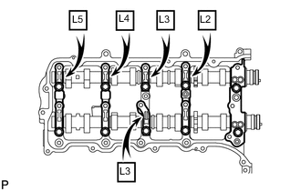
Confirm the marks and numbers on the camshaft bearing caps and place them in their proper positions and directions.
-
Temporarily install the 10 bolts in the order shown in the illustration.
-
-
INSTALL CAMSHAFT HOUSING SUB-ASSEMBLY LH
-
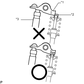
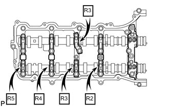
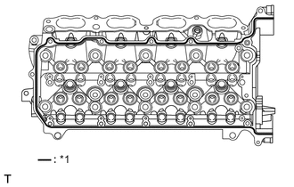
Text in Illustration *1 Valve Rocker Arm *2 Valve Stem Cap *3 Valve Lash Adjuster Check the valve rocker arms as shown in the illustration.
-
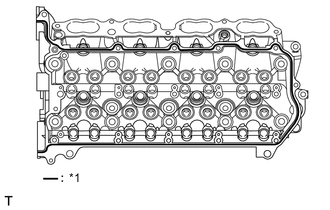
Text in Illustration *1 Seal Packing Apply seal packing in a continuous line as shown in the illustration.
Seal packing Toyota Genuine Seal Packing Black, Three Bond 1207B or equivalent Standard seal diameter 3.5 to 4.0 mm (0.138 to 0.157 in.) Note
-
Remove any oil from the contact surface.
-
Install the camshaft housing within 3 minutes and tighten the bolts within 15 minutes after applying seal packing.
-
-
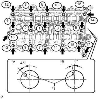
Text in Illustration *A for Intake Side *B for Exhaust Side *1 Knock Pin 
Bolt 
Bolt A Install the camshaft housing, and then install the 18 bolts in the order shown in the illustration.
- Torque:
- for bolt A
- 10 N*m { 102 kgf*cm, 7 ft.*lbf }
- except bolt A
- 30 N*m { 306 kgf*cm, 22 ft.*lbf }
Note
-
Do not start the engine for at least 2 hours after the installation.
-
Make sure that the knock pins of the camshafts are positioned as shown in the illustration before installing the camshaft housing.
-
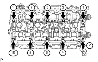
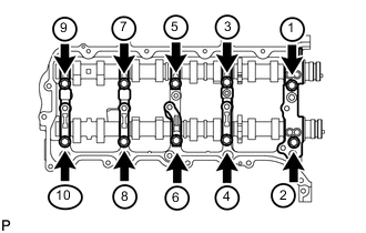
Tighten the 10 bolts in the order shown in the illustration.
- Torque:
- 16 N*m { 163 kgf*cm, 12 ft.*lbf }
Note
Thoroughly wipe clean any seal packing.
-
-
INSTALL CAMSHAFT BEARING CAP RH
-
Apply a light coat of engine oil to the camshaft journals, camshaft housing and camshaft bearing caps.
-
Install the No. 1 and No. 2 camshafts to the camshaft housing.
-
Confirm the marks and numbers on the camshaft bearing caps and place them in their proper positions and directions.
-
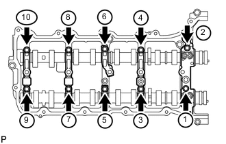
Temporarily install the 10 bolts in the order shown in the illustration.
-
-
INSTALL CAMSHAFT HOUSING SUB-ASSEMBLY RH
-
Text in Illustration *1 Valve Rocker Arm *2 Valve Stem Cap *3 Valve Lash Adjuster Check the valve rocker arms as shown in the illustration.
-
Text in Illustration *1 Seal Packing Apply seal packing in a continuous line as shown in the illustration.
Seal packing Toyota Genuine Seal Packing Black, Three Bond 1207B or equivalent Standard seal diameter 3.5 to 4.0 mm (0.138 to 0.157 in.) Note
-
Remove any oil from the contact surface.
-
Install the camshaft housing within 3 minutes and tighten the bolts within 15 minutes after applying seal packing.
-
-
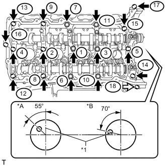
Text in Illustration *A for Exhaust Side *B for Intake Side *1 Knock Pin Bolt Bolt A Install the camshaft housing, and then install the 18 bolts in the order shown in the illustration.
- Torque:
- for bolt A
- 10 N*m { 102 kgf*cm, 7 ft.*lbf }
- except bolt A
- 30 N*m { 306 kgf*cm, 22 ft.*lbf }
Note
-
Do not start the engine for at least 2 hours after the installation.
-
Make sure that the knock pins of the camshafts are positioned as shown in the illustration before installing the camshaft housing.
-
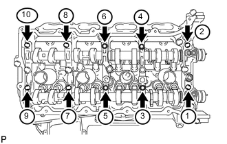
Tighten the 10 bolts in the order shown in the illustration.
- Torque:
- 16 N*m { 163 kgf*cm, 12 ft.*lbf }
Note
Thoroughly wipe clean any seal packing.
-
-
INSTALL NO. 2 CHAIN TENSIONER ASSEMBLY
-
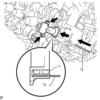
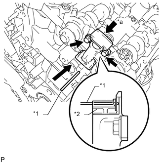
Text in Illustration *1 Plunger *2 Pin *a Push Install the No. 2 chain tensioner with the 2 bolts.
- Torque:
- 10 N*m { 102 kgf*cm, 7 ft.*lbf }
-
While raising up the No. 2 chain tensioner, insert a pin with a diameter of 1.0 mm (0.0394 in.) into the hole to fix the tensioner in place.
-
-
INSTALL NO. 1 CHAIN SUB-ASSEMBLY RH
-
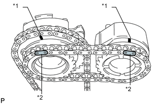
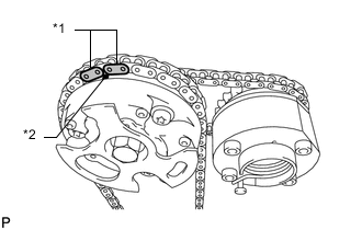
Text in Illustration *1 Mark Plate (Orange) *2 Timing Mark Align the No. 1 chain's mark plates (orange) with the camshaft timing gear's timing mark and attach the chain to the gear as shown in the illustration.
-
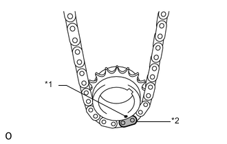
Text in Illustration *1 Timing Mark *2 Mark Plate (Orange) Align the No. 1 chain's mark plate (orange) with the crankshaft timing gear's timing mark and attach the chain to the gear as shown in the illustration.
-
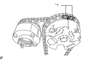
Text in Illustration *1 Timing Mark *2 Mark Plate (Yellow) Align the No. 2 chain's mark plates (yellow) with the timing marks (1-dot marks) of the camshaft timing gear and camshaft timing exhaust gear, and attach the No. 2 chain to the gears as shown in the illustration.
Tech Tips
The crankshaft timing gear and camshaft exhaust gear are installed with the No. 1 and No. 2 chains connected to the gears.
-
Install the crankshaft timing sprocket RH to the crankshaft.
-
Align the knock pin of the No. 1 camshaft with the pin hole of the camshaft timing gear and install the camshaft timing gear.
-
Using the hexagonal portion of the No. 2 camshaft, align the knock pin of the No. 2 camshaft with the pin hole of the camshaft timing exhaust gear and install the camshaft timing exhaust gear.
-
Remove the pin from the No. 2 chain tensioner.
-
-
INSTALL NO. 1 CHAIN VIBRATION DAMPER RH
-
Install the No. 1 chain vibration damper RH with the 2 bolts.
- Torque:
- 21 N*m { 214 kgf*cm, 15 ft.*lbf }
-
-
INSTALL CHAIN TENSIONER SLIPPER RH
Tech Tips
If the No. 1 chain tensioner slipper cannot be installed due to the tension of the chain, use the hexagonal portion of the camshaft to loosen the chain, and then install the chain tensioner slipper RH.
-
INSTALL NO. 1 CHAIN TENSIONER ASSEMBLY RH
-

Text in Illustration *1 Stopper Plate *2 Plunger Move the stopper plate upward to release the lock and push the plunger deep into the No. 1 chain tensioner.
-
Move the stopper plate downward to set the lock and insert a hexagon wrench into the hole of the stopper plate.
-
Install the No. 1 chain tensioner with the 2 bolts.
- Torque:
- 10 N*m { 102 kgf*cm, 7 ft.*lbf }
-
Remove the hexagon wrench from the No. 1 chain tensioner.
-
-
INSTALL NO. 3 CHAIN TENSIONER ASSEMBLY
-
Text in Illustration *1 Pin *2 Plunger *a Push Install the No. 3 chain tensioner with the 2 bolts.
- Torque:
- 10 N*m { 102 kgf*cm, 7 ft.*lbf }
-
While pushing down the No. 3 chain tensioner, insert a pin with a diameter of 1.0 mm (0.0394 in.) into the hole to fix the tensioner in place.
-
-
INSTALL NO. 1 CHAIN SUB-ASSEMBLY LH
-
Text in Illustration *1 Mark Plate (Orange) *2 Timing Mark Align the No. 1 chain's mark plates (orange) with the camshaft timing gear's timing mark and attach the chain to the gear as shown in the illustration.
-
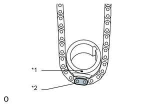
Text in Illustration *1 Timing Mark *2 Mark Plate (Orange) Align the No. 1 chain's mark plate (orange) with the crankshaft timing gear's timing mark and attach the chain to the gear as shown in the illustration.
-
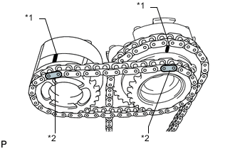
Text in Illustration *1 Timing Mark *2 Mark Plate (Yellow) Align the No. 2 chain's mark plates (yellow) with the timing marks (1-dot marks) of the camshaft timing gear and camshaft timing exhaust gear, and attach the No. 2 chain to the gears as shown in the illustration.
Tech Tips
The crankshaft timing gear and camshaft exhaust gear are installed with the No. 1 and No. 2 chains connected to the gears.
-
Install the crankshaft timing sprocket LH to the crankshaft.
-
Align the knock pin of the No. 3 camshaft with the pin hole of the camshaft timing gear and install the camshaft timing gear.
-
Using the hexagonal portion of the No. 4 camshaft, align the knock pin of the No. 4 camshaft with the pin hole of the camshaft timing exhaust gear and install the camshaft timing exhaust gear.
Note
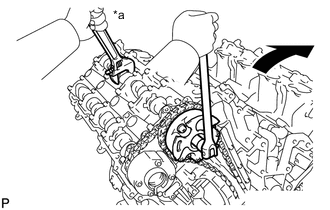
Because the gears' timing mark positions may shift due to looseness of the No. 1 chain, use the hexagonal portion of the camshaft to hold the No. 3 camshaft in place until the No. 1 chain tensioner is installed.
-
Remove the pin from the No. 3 chain tensioner.
-
-
INSTALL CHAIN TENSIONER SLIPPER LH
Tech Tips
If the chain tensioner slipper cannot be installed due to the tension of the chain, use the hexagonal portion of the camshaft to loosen the chain and install the chain tensioner slipper LH.
-
INSTALL NO. 1 CHAIN TENSIONER ASSEMBLY LH
-
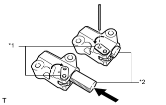
Text in Illustration *1 Stopper Plate *2 Plunger Move the stopper plate upward to release the lock and push the plunger deep into the No. 1 chain tensioner.
-
Move the stopper plate downward to set the lock and insert a hexagon wrench into the hole of the stopper plate.
-
Install a new gasket and the No. 1 chain tensioner with the 2 bolts.
- Torque:
- 10 N*m { 102 kgf*cm, 7 ft.*lbf }
-
-
INSTALL NO. 1 CHAIN VIBRATION DAMPER LH
-
Install the No. 1 chain vibration damper with the 2 bolts.
- Torque:
- 21 N*m { 214 kgf*cm, 15 ft.*lbf }
-
Remove the hexagon wrench from the No. 1 chain tensioner.
-
-
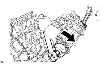
TIGHTEN CAMSHAFT TIMING GEAR ASSEMBLY
-
for Bank 1:
-
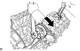
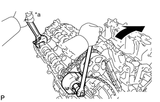
Text in Illustration *a Hold Turn Using a wrench to hold the hexagonal portion of the No. 3 camshaft, install the camshaft timing gear bolt.
- Torque:
- 100 N*m { 1020 kgf*cm, 74 ft.*lbf }
-
Text in Illustration *a Hold Turn Using a wrench to hold the hexagonal portion of the No. 4 camshaft, install the camshaft timing exhaust gear bolt.
- Torque:
- 100 N*m { 1020 kgf*cm, 74 ft.*lbf }
-
-
for Bank 2:
-
Text in Illustration *a Hold Turn Using a wrench to hold the hexagonal portion of the No. 1 camshaft, install the camshaft timing gear bolt.
- Torque:
- 100 N*m { 1020 kgf*cm, 74 ft.*lbf }
-
Text in Illustration *a Hold Turn Using a wrench to hold the hexagonal portion of the No. 2 camshaft, install the camshaft timing exhaust gear bolt.
- Torque:
- 100 N*m { 1020 kgf*cm, 74 ft.*lbf }
-
-
-
CHECK NO. 1 CYLINDER TO TDC/COMPRESSION
-
INSTALL TIMING CHAIN COVER SUB-ASSEMBLY
-
INSPECT IGNITION TIMING
-
INSPECT ENGINE IDLE SPEED