CAMSHAFT REMOVAL
PROCEDURE
-
REMOVE TIMING CHAIN COVER SUB-ASSEMBLY
-
SET NO. 1 CYLINDER TO TDC/COMPRESSION
-
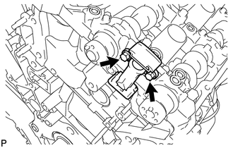
REMOVE NO. 1 CHAIN TENSIONER ASSEMBLY LH
-
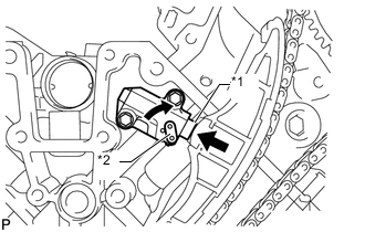
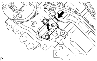
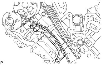
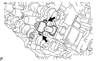
Text in Illustration *1 Plunger *2 Stopper Plate Move the stopper plate upward to release the lock and push the plunger deep into the No. 1 chain tensioner.
-
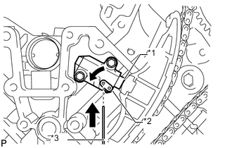
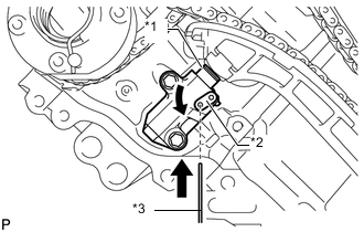
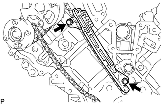
Text in Illustration *1 Plunger *2 Stopper Plate *3 Hexagon Wrench Move the stopper plate downward to set the lock and insert a hexagon wrench into the stopper plate hole.
-
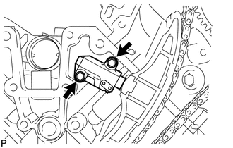
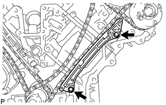
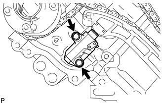
Remove the 2 bolts, No. 1 chain tensioner LH and gasket.
-
-
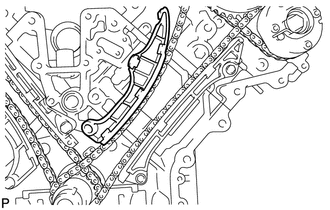
REMOVE CHAIN TENSIONER SLIPPER LH
-
REMOVE NO. 1 CHAIN VIBRATION DAMPER LH
-
Remove the 2 bolts and No. 1 chain vibration damper LH.
-
-
REMOVE NO. 1 CHAIN SUB-ASSEMBLY LH
-
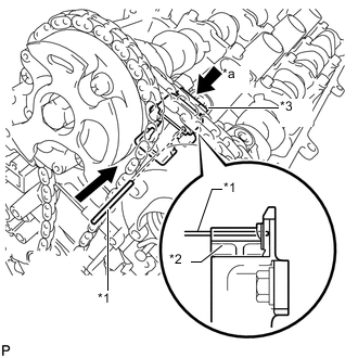
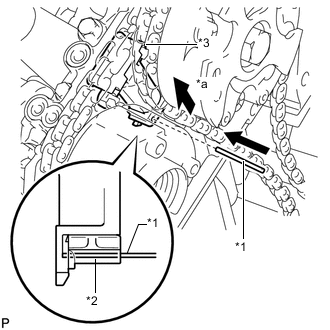
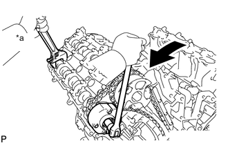
Text in Illustration *1 Pin *2 Plunger *3 No. 3 Chain Tensioner *a Push While pushing down the No. 3 chain tensioner, insert a pin with a diameter of 1.0 mm (0.0394 in.) into the hole to fix the tensioner in place.
-
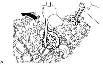
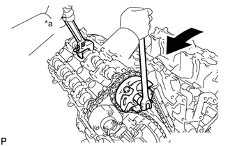
Text in Illustration *a Hold 
Turn Hold the hexagonal portion of the camshaft with a wrench and loosen the bolt.
Note
-
Be careful not to damage the cylinder head with the wrench.
-
Do not disassemble the camshaft timing gear.
-
-
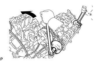
Text in Illustration *a Hold Turn Hold the hexagonal portion of the camshaft with a wrench and loosen the bolt.
Note
-
Be careful not to damage the cylinder head with the wrench.
-
Do not disassemble the camshaft timing exhaust gear.
-
-
Remove the 2 bolts. Then with the No. 1 and No. 2 chains still connected to the gears, remove the camshaft timing gear, camshaft timing exhaust gear and crankshaft timing sprocket LH.
-
Remove the No. 1 and No. 2 chains from the gears.
-
-
REMOVE NO. 3 CHAIN TENSIONER ASSEMBLY
-
Remove the 2 bolts and No. 3 chain tensioner.
-
-
REMOVE NO. 1 CHAIN TENSIONER ASSEMBLY RH
-
Text in Illustration *1 Plunger *2 Stopper Plate Move the stopper plate upward to release the lock and push the plunger deep into the No. 1 chain tensioner.
-
Text in Illustration *1 Plunger *2 Stopper Plate *3 Hexagon Wrench Move the stopper plate downward to set the lock and insert a hexagon wrench into the stopper plate hole.
-
Remove the 2 bolts and No. 1 chain tensioner RH.
-
-
REMOVE CHAIN TENSIONER SLIPPER RH
-
REMOVE NO. 1 CHAIN VIBRATION DAMPER RH
-
Remove the 2 bolts and No. 1 chain vibration damper RH.
-
-
REMOVE NO. 1 CHAIN SUB-ASSEMBLY RH
-
Text in Illustration *1 Pin *2 Plunger *3 No. 2 Chain Tensioner *a Push While raising up the No. 2 chain tensioner, insert a pin with a diameter of 1.0 mm (0.0394 in.) into the hole to fix the tensioner in place.
-
Text in Illustration *a Hold Turn Hold the hexagonal portion of the camshaft with a wrench and loosen the bolt.
Note
-
Be careful not to damage the cylinder head with the wrench.
-
Do not disassemble the camshaft timing gear.
-
-
Text in Illustration *a Hold Turn Hold the hexagonal portion of the camshaft with a wrench and loosen the bolt.
Note
-
Be careful not to damage the cylinder head with the wrench.
-
Do not disassemble the camshaft timing exhaust gear.
-
-
Remove the 2 bolts. Then with the No. 1 and No. 2 chains still connected to the gears, remove the camshaft timing gear, camshaft timing exhaust gear and crankshaft timing sprocket RH.
-
Remove the No. 1 and No. 2 chains from the gears.
-
-
REMOVE NO. 2 CHAIN TENSIONER ASSEMBLY
-
Remove the 2 bolts and No. 2 chain tensioner.
-
-
REMOVE CAMSHAFT BEARING CAP LH
-
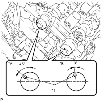
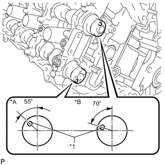
Text in Illustration *A for Intake Side *B for Exhaust Side *1 Knock Pin Make sure that the knock pins of the camshafts are positioned as shown in the illustration.
-
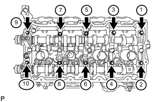
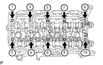
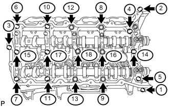
Uniformly loosen and remove the 10 bearing cap bolts in the sequence shown in the illustration.
-
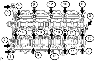
Uniformly loosen and remove the 18 bearing cap bolts in the sequence shown in the illustration.
Note
Uniformly loosen the bolts while keeping the camshaft level.
-
Remove the 6 camshaft bearing caps.
Tech Tips
Arrange the removed parts in the correct order.
-
-
REMOVE NO. 3 CAMSHAFT SUB-ASSEMBLY
-
Remove the No. 3 camshaft from the camshaft housing LH.
-
-
REMOVE NO. 4 CAMSHAFT SUB-ASSEMBLY
-
Remove the No. 4 camshaft from the camshaft housing LH.
-
-
REMOVE CAMSHAFT HOUSING SUB-ASSEMBLY LH
-
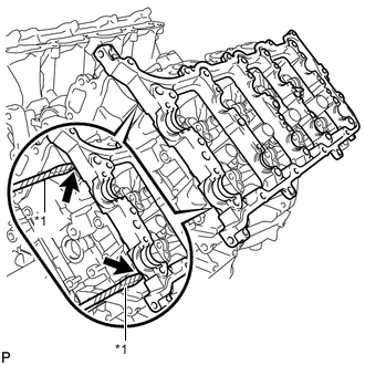
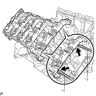
Text in Illustration *1 Protective Tape Remove the camshaft housing by prying between the cylinder head and camshaft housing with a screwdriver.
Note
Be careful not to damage the contact surfaces of the cylinder head and camshaft housing.
Tech Tips
Tape the screwdriver tip before use.
-
-
REMOVE CAMSHAFT BEARING CAP RH
-
Text in Illustration *A for Exhaust Side *B for Intake Side *1 Knock Pin Make sure that the knock pins of the camshafts are positioned as shown in the illustration.
-
Uniformly loosen and remove the 10 bearing cap bolts in the sequence shown in the illustration.
-
Uniformly loosen and remove the 18 bearing cap bolts in the sequence shown in the illustration.
Note
Uniformly loosen the bolts while keeping the camshaft level.
-
Remove the 6 camshaft bearing caps.
Tech Tips
Arrange the removed parts in the correct order.
-
-
REMOVE NO. 1 CAMSHAFT SUB-ASSEMBLY
-
Remove the No. 1 camshaft from the camshaft housing RH.
-
-
REMOVE NO. 2 CAMSHAFT SUB-ASSEMBLY
-
Remove the No. 2 camshaft from the camshaft housing RH.
-
-
REMOVE CAMSHAFT HOUSING SUB-ASSEMBLY RH
-
Text in Illustration *1 Protective Tape Remove the camshaft housing by prying between the cylinder head and camshaft housing with a screwdriver.
Note
Be careful not to damage the contact surfaces of the cylinder head and camshaft housing.
Tech Tips
Tape the screwdriver tip before use.
-
-
INSPECT CAMSHAFT TIMING GEAR ASSEMBLY
-
INSPECT CAMSHAFT TIMING EXHAUST GEAR ASSEMBLY