ENGINE ASSEMBLY INSTALLATION

PROCEDURE
-
INSTALL FRONT NO. 2 ENGINE MOUNTING BRACKET LH
-
Install the front No. 2 engine mounting bracket LH with the bolt.
- Torque:
- 32 N*m { 326 kgf*cm, 24 ft.*lbf }
-
-
INSTALL ENGINE HANGER
-
REMOVE ENGINE STAND
-
Attach an engine sling device and hang the engine with a chain block.
-
Lift the engine and remove it from the engine stand.
Note
-
With the exception of installing the engine assembly to an engine stand or removing the engine assembly from an engine stand, do not perform any work on the engine while it is suspended, as doing so is dangerous.
-
Pay attention to the angle of the sling device as the engine assembly or engine hangers may be damaged or deformed if the angle is incorrect.
-
-
Place the engine onto a work bench.
-
-
INSTALL ENGINE ASSEMBLY
-
Slowly lower the engine into the engine compartment.
-
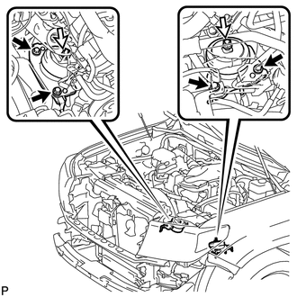
Install the front engine mounting insulator LH with the 2 bolts and nut.
- Torque:
- for bolt
- 79 N*m { 806 kgf*cm, 58 ft.*lbf }
- for nut
- 72 N*m { 734 kgf*cm, 53 ft.*lbf }
Text in Illustration 
Bolt 
Nut -
Install the front engine mounting insulator RH with the 2 bolts and nut.
- Torque:
- for bolt
- 79 N*m { 806 kgf*cm, 58 ft.*lbf }
- for nut
- 72 N*m { 734 kgf*cm, 53 ft.*lbf }
-
Remove the 2 engine hangers and 4 bolts.
-
-
INSTALL DRIVE PLATE AND RING GEAR SUB-ASSEMBLY
-
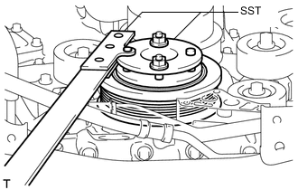
Using SST, hold the crankshaft.
- SST
- 09213-54015 ( 91651-60855 )
- 09330-00021
-
Clean the bolts and their installation holes.
-
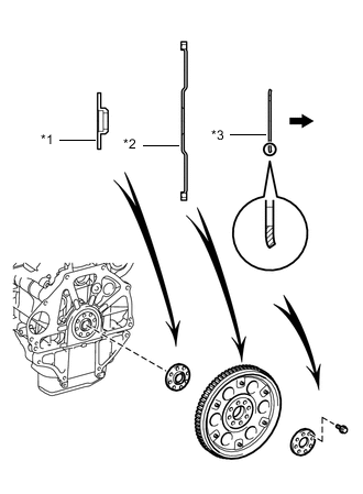
Text in Illustration *1 Front Spacer *2 Drive Plate and Ring Gear *3 Rear Spacer Automatic Transmission Side Install the front spacer, drive plate and rear spacer to the crankshaft.
Tech Tips
As the front spacer, the drive plate and ring gear, and the rear spacer are not reversible, be sure to install them in the direction shown in the illustration.
-
Apply adhesive to 2 or 3 threads at the end of the 8 new bolts.
Adhesive Toyota Genuine Adhesive 1324, Three Bond 1324 or equivalent -
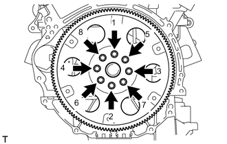
Uniformly install and tighten the 8 bolts in several steps in the sequence shown in the illustration.
- Torque:
- 83 N*m { 846 kgf*cm, 61 ft.*lbf }
Note
Do not start the engine for at least 1 hour after installing.
-
-
CONNECT NO. 1 OIL COOLER HOSE TUBE SUB-ASSEMBLY
-
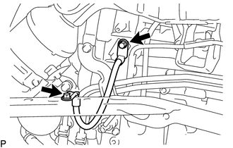
Connect the cooler hose tube with the 2 bolts.
- Torque:
- 14 N*m { 143 kgf*cm, 10 ft.*lbf }
-
-
INSTALL REAR NO. 1 ENGINE MOUNTING INSULATOR
-
Install the rear No. 1 engine mounting insulator to the transmission with the 4 bolts.
- Torque:
- 59 N*m { 602 kgf*cm, 44 ft.*lbf }
-
-
INSTALL AUTOMATIC TRANSMISSION ASSEMBLY
-
CONNECT NO. 1 AND NO. 2 FUEL PIPE
-
Connect the No. 1 and No. 2 fuel pipes Click here.
-
-
INSTALL COOLER COMPRESSOR ASSEMBLY
-
CONNECT SUCTION HOSE SUB-ASSEMBLY
-
CONNECT NO. 1 COOLER REFRIGERANT DISCHARGE HOSE
-
INSTALL GENERATOR ASSEMBLY
-
CONNECT VANE PUMP ASSEMBLY
-
CONNECT WATER HOSE SUB-ASSEMBLY
-
Connect the water hoses.
-
-
INSTALL EXHAUST MANIFOLD SUB-ASSEMBLY LH
-
INSTALL NO. 2 EXHAUST MANIFOLD HEAT INSULATOR
-
INSTALL NO. 2 AIR TUBE (w/ Secondary Air Injection System)
-
INSTALL NO. 2 MANIFOLD STAY
-
INSTALL EXHAUST MANIFOLD SUB-ASSEMBLY RH
-
INSTALL NO. 1 EXHAUST MANIFOLD HEAT INSULATOR
-
CONNECT NO. 2 STEERING INTERMEDIATE SHAFT
-
INSTALL AIR TUBE (w/ Secondary Air Injection System)
-
INSTALL MANIFOLD STAY
-
INSTALL FRONT FENDER APRON TRIM PACKING D
-
INSTALL FRONT FENDER APRON TRIM PACKING C
-
INSTALL FRONT FENDER APRON TRIM PACKING B
-
INSTALL FRONT FENDER APRON TRIM PACKING A
-
INSTALL FRONT EXHAUST PIPE ASSEMBLY
-
INSTALL HEATED OXYGEN SENSOR (for Bank 2 Sensor 2)
-
INSTALL FRONT NO. 2 EXHAUST PIPE ASSEMBLY
-
INSTALL CENTER EXHAUST PIPE ASSEMBLY
-
INSTALL TAILPIPE ASSEMBLY
-
INSTALL HEATED OXYGEN SENSOR (for Bank 1 Sensor 2)
-
CONNECT ENGINE WIRE
-
w/ Secondary Air Injection System:
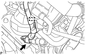
Attach the clamp and connect the air pump connector.
-
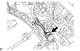
Attach the clamp and connect the power steering switch connector.
-
w/ Winch:
Install the winch ground wire with the 2 bolts.
- Torque:
- 19 N*m { 196 kgf*cm, 14 ft.*lbf }
-
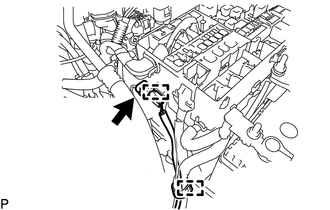
Attach the 2 clamps and connect the connector.
-
Install the ground wire with the bolt and attach the wire harness clamp.
- Torque:
- 8.4 N*m { 86 kgf*cm, 74 in.*lbf }
-
Connect the cable to the positive (+) battery terminal.
-
Connect the wire to the positive (+) battery cable with the nut.
- Torque:
- 7.5 N*m { 76 kgf*cm, 66 in.*lbf }
-
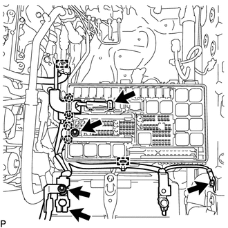
Connect the wire and 2 clips to the engine room junction block with the nut.
- Torque:
- 7.5 N*m { 76 kgf*cm, 66 in.*lbf }
-
Connect the 2 clips and 2 connectors to the engine room junction block.
-
w/ Secondary Air Injection System:
Attach the clamp and connect the 2 air injection control driver connectors.
-
Connect the ground wire to the bracket with the bolt.
- Torque:
- 5.0 N*m { 51 kgf*cm, 44 in.*lbf }
-
Install the engine room relay block cover.
-
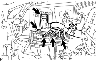
Connect the 4 connectors to the junction block.
-
Attach the wire harness clamp.
-
Connect the ECM connector Click here.
-
Install the junction block cover.
-
-
INSTALL INTAKE AIR SURGE TANK
-
INSTALL AIR TUBE ASSEMBLY (w/ Secondary Air Injection System)
-
INSTALL AIR CLEANER CASE SUB-ASSEMBLY
-
Install the air cleaner case with the 3 bolts.
- Torque:
- 5.0 N*m { 51 kgf*cm, 44 in.*lbf }
-
Install the air cleaner filter element.
-
-
INSTALL AIR CLEANER CAP AND HOSE
-
Install the air cleaner cap and hose.
-
Install the air cleaner cap and hose with the bolt and fasten the 4 hook clamps.
- Torque:
- 5.0 N*m { 51 kgf*cm, 44 in.*lbf }
-
Tighten the clamp.
- Torque:
- 2.5 N*m { 25 kgf*cm, 22 in.*lbf }
-
Attach the clamp and connect the ventilation hose, vacuum hose and mass air flow meter connector.
-
-
-
INSTALL RADIATOR ASSEMBLY
-
CONNECT OUTLET OIL COOLER HOSE
-
CONNECT INLET OIL COOLER HOSE
-
INSTALL FAN SHROUD
-
CONNECT OIL COOLER TUBE (w/ Air Cooled Transmission Oil Cooler)
-
INSTALL NO. 2 RADIATOR HOSE
-
INSTALL NO. 1 RADIATOR HOSE
-
INSTALL RADIATOR SIDE DEFLECTOR LH
-
INSTALL RADIATOR SIDE DEFLECTOR RH (w/o Air Cooled Transmission Oil Cooler)
-
INSTALL TRANSMISSION OIL COOLER AIR DUCT (w/ Air Cooled Transmission Oil Cooler)
-
INSTALL V-BANK COVER
-
INSTALL FRONT BUMPER COVER
-
for Standard Click here
-
w/ Winch Click here
-
-
INSTALL RADIATOR GRILLE
-
INSTALL UPPER RADIATOR SUPPORT SEAL
-
INSTALL NO. 2 ENGINE UNDER COVER
-
Install the No. 2 engine under cover with the 2 bolts.
- Torque:
- 29 N*m { 296 kgf*cm, 21 ft.*lbf }
-
-
INSTALL NO. 1 ENGINE UNDER COVER SUB-ASSEMBLY
-
INSTALL FRONT FENDER SPLASH SHIELD SUB-ASSEMBLY LH
-
INSTALL FRONT FENDER SPLASH SHIELD SUB-ASSEMBLY RH
-
INSTALL COWL TOP VENTILATOR LOUVER SUB-ASSEMBLY
-
CONNECT CABLE TO NEGATIVE BATTERY TERMINAL
Note
When disconnecting the cable, some systems need to be initialized after the cable is reconnected Click here.
-
ADD ENGINE OIL
-
ADD ENGINE COOLANT
-
INSPECT FOR FUEL LEAK
-
INSPECT FOR COOLANT LEAK
-
INSPECT FOR OIL LEAK
-
INSPECT FOR EXHAUST GAS LEAK
-
CHECK ENGINE OIL LEVEL
-
CHARGE REFRIGERANT
-
WARM UP ENGINE
-
CHECK FOR REFRIGERANT GAS LEAK
-
PERFORM RESET MEMORY
-
Perform the Reset Memory procedures Click here.
-
-
INSPECT IGNITION TIMING
-
INSPECT ENGINE IDLE SPEED
-
INSPECT CO/HC
-
INSTALL HOOD SUB-ASSEMBLY
-
Install the hood with the 4 bolts.
- Torque:
- 18 N*m { 178 kgf*cm, 13 ft.*lbf }
-
-
INSPECT HOOD SUB-ASSEMBLY
-
ADJUST HOOD SUB-ASSEMBLY
-
INSPECT RESERVOIR TANK ENGINE COOLANT LEVEL