Click here
PROCEDURE
- Click here
REMOVE V-BANK COVER SUB-ASSEMBLY
-
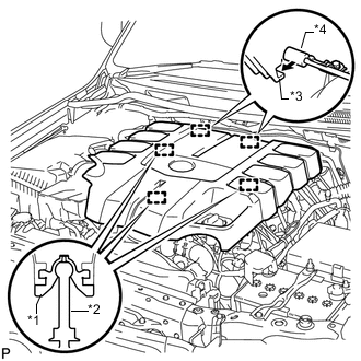
Raise the front of the V-bank cover to detach the 3 pins. Then remove the 2 V-bank cover hooks from the bracket, and remove the V-bank cover.
Table 1. Text in Illustration *1 Grommet *2 Pin *3 Hook *4 Bracket
-
- Click here
REMOVE FRONT FENDER SPLASH SHIELD SUB-ASSEMBLY LH
- Click here
REMOVE FRONT FENDER SPLASH SHIELD SUB-ASSEMBLY RH
- Click here
REMOVE NO. 1 ENGINE UNDER COVER SUB-ASSEMBLY
- Click here
REMOVE FAN AND GENERATOR V BELT
-
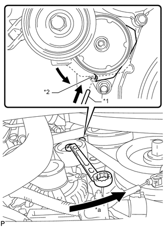
While turning the belt tensioner counterclockwise, align the service hole for the belt tensioner and the belt tensioner fixing position, and then insert a bar with a diameter of 5 mm (0.197 in.) into the service hole to fix the belt tensioner in place.
Table 2. Text in Illustration *1 Bar *2 Service Hole *a Turn Tip:The pulley bolt for the belt tensioner has a left-hand thread.
-
Remove the fan and generator V belt.
-