DIESEL THROTTLE BODY INSTALLATION
CAUTION / NOTICE / HINT
Note
Disconnect the cable from the negative (-) battery terminal to clear the diesel throttle valve fully closed position learned value.
PROCEDURE
-
INSTALL DIESEL THROTTLE BODY ASSEMBLY LH
-
Install a new gasket to the intake pipe.
-
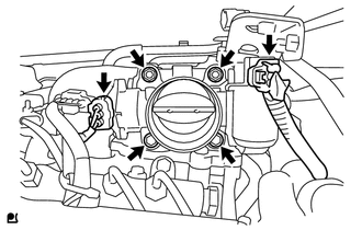
Install the throttle body with the 2 bolts and 2 nuts.
- Torque:
- 21 N*m { 214 kgf*cm, 15 ft.*lbf }
-
Connect the throttle position sensor connector.
-
Connect the throttle motor connector.
-
-
INSTALL DIESEL THROTTLE BODY ASSEMBLY RH
-
Install a new gasket to the intake pipe.
-
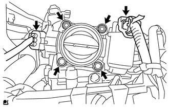
Install the throttle body with the 2 bolts and 2 nuts.
- Torque:
- 21 N*m { 214 kgf*cm, 15 ft.*lbf }
-
Connect the throttle position sensor connector.
-
Connect the throttle motor connector.
-
-
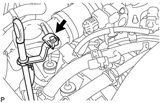
INSTALL TUBE CONNECTOR TO FLEXIBLE HOSE TUBE (for Manual Transmission)
-
Temporarily install the flare nut of the tube connector to flexible hose tube to the clutch tube to release cylinder 2 way by hand.
-
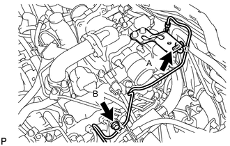
Temporarily install the tube connector to flexible hose tube with the 2 bolts.
-
Tighten the bolt labeled A.
- Torque:
- 20 N*m { 204 kgf*cm, 15 ft.*lbf }
Note
Tighten the bolt labeled B after installing the clutch hose.
-
-
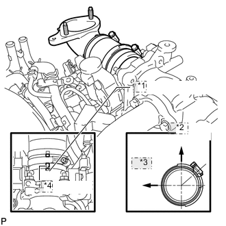
INSTALL AIR TUBE SUB-ASSEMBLY LH
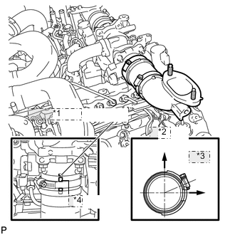
*1 Embossed Mark *2 Upper *3 Front *4 Paint Mark
-
Install the air tube to the throttle body.
-
Align the embossed mark of the throttle body with the paint mark of the No. 4 air hose.
-
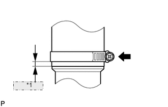
*1 7 to 11 mm Tighten the hose clamp so that it is 7 to 11 mm (0.276 to 0.433 in.) from the end of the hose as shown in the illustration.
- Torque:
- 6.3 N*m { 64 kgf*cm, 56 in.*lbf }
-
-
INSTALL CLUTCH HOSE (for Manual Transmission)
-
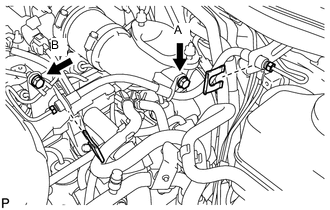
Connect the clutch hose to the air tube with the bolt labeled A.
-
Temporarily install the clutch hose to the clutch master cylinder tube to flexible hose tube and tube connector to flexible hose tube, and fix it in place with the 2 clips.
- Torque:
- 20 N*m { 204 kgf*cm, 15 ft.*lbf }
-
Tighten the bolt labeled B.
- Torque:
- 20 N*m { 204 kgf*cm, 15 ft.*lbf }
-
Tighten the flexible hose tube.
Note
-
Do not bend or damage the flexible hose tube.
-
Do not allow any foreign matter such as dirt and dust to enter the flexible hose tube from the connecting points.
Tech Tips
-
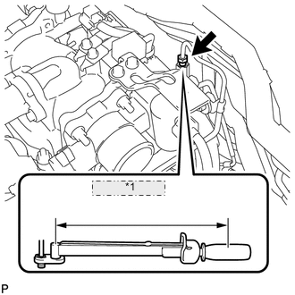
Use a torque wrench with a fulcrum length of 30 cm (11.8 in.). If using a torque wrench with a length that is not 30 cm (11.8 in.), calculate the torque specification for the torque wrench and SST based on the "without SST" torque specification Click here.
-
Make sure union nut wrench and the wrench are connected in a straight line.
-
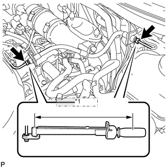
*1 Fulcrum Length Using a 10 mm union nut wrench, tighten the 2 flare nuts of the flexible hose tube.
- Torque:
- without union nut wrench
- 15 N*m { 154 kgf*cm, 11 ft.*lbf }
- with union nut wrench
- 14 N*m { 141 kgf*cm, 10 ft.*lbf }
-
*1 Fulcrum Length Using a 10 mm union nut wrench, tighten the flare nut of the flexible hose tube.
- Torque:
- without union nut wrench
- 15 N*m { 154 kgf*cm, 11 ft.*lbf }
- with union nut wrench
- 14 N*m { 141 kgf*cm, 10 ft.*lbf }
-
-
-
INSTALL AIR TUBE SUB-ASSEMBLY RH
*1 Embossed Mark *2 Upper *3 Front *4 Paint Mark
-
Install the air tube to the throttle body.
-
Align the embossed mark of the throttle body with the paint mark of the No. 4 air hose.
-
*1 7 to 11 mm Tighten the hose clamp so that it is 7 to 11 mm (0.276 to 0.433 in.) from the end of the hose as shown in the illustration.
- Torque:
- 6.3 N*m { 64 kgf*cm, 56 in.*lbf }
-
-
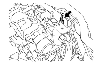
CONNECT NO. 2 ENGINE OIL LEVEL DIPSTICK GUIDE
-
Connect the dipstick guide with the bolt.
- Torque:
- 10 N*m { 102 kgf*cm, 7 ft.*lbf }
-
-
INSTALL NO. 1 COOL AIR INLET (w/o Intercooler)
-
INSTALL NO. 2 COOL AIR INLET (w/o Intercooler)
-
INSTALL INTERCOOLER ASSEMBLY (w/ Intercooler)
-
FILL BRAKE FLUID RESERVOIR
-
BLEED CLUTCH LINE
-
CHECK FLUID LEVEL IN RESERVOIR
-
INSPECT FOR CLUTCH FLUID LEAK
-
CONNECT CABLE TO NEGATIVE BATTERY TERMINAL
Note
When disconnecting the cable, some systems need to be initialized after the cable is reconnected Click here.
-
CHECK DIESEL THROTTLE BODY ASSEMBLY
-
PERFORM DIESEL THROTTLE BODY INITIALIZATION