ECD SYSTEM(w/o DPF), Diagnostic DTC:P1495, P1496, P1497
| DTC Code | DTC Name |
|---|---|
| P1495 | Intake Air Temperature Sensor 1 Circuit |
| P1496 | Intake Air Temperature Sensor 1 Circuit Low |
| P1497 | Intake Air Temperature Sensor 1 Circuit High |
DESCRIPTION
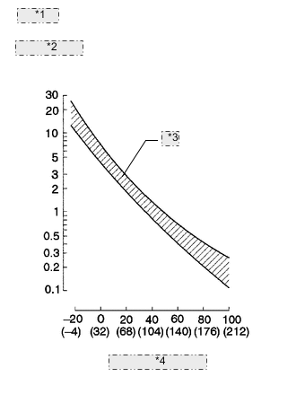
| *1 | (Fig. 1) |
| *2 | Resistance kΩ |
| *3 | Acceptable |
| *4 | Temperature °C (°F) |
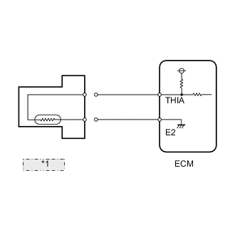
The Intake Air Temperature (IAT) sensor is built into the charge air cooler and senses the IAT. A built-in thermistor in the sensor changes its resistance value according to the intake air temperature. The lower the intake air temperature, the greater the thermistor resistance value. The higher the intake air temperature, the lower the thermistor resistance value (See Fig. 1).
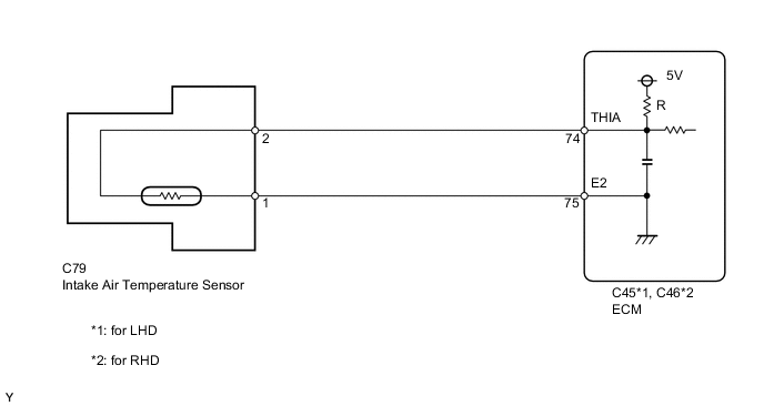
The sensor is connected to the ECM. The 5 V power source voltage in the ECM is applied to the sensor from terminal THIA via resistor R. Resistor R and the sensor are connected in series. When the resistance value of the sensor changes in accordance with changes in the IAT, the potential at terminal THIA also changes. Based on this signal, the ECM corrects the fuel injection volume to improve driveability with a cold engine.
| DTC Detection Drive Pattern | DTC Detection Condition | Trouble Area |
|---|---|---|
| Ignition switch ON for 1 second | Open or short in the intake air temperature (IAT) sensor circuit for 0.5 seconds (1 trip detection logic). |
|
| DTC Detection Drive Pattern | DTC Detection Condition | Trouble Area |
|---|---|---|
| Ignition switch ON for 1 second | Short in the IAT sensor circuit for 0.5 seconds (1 trip detection logic). |
|
| DTC Detection Drive Pattern | DTC Detection Condition | Trouble Area |
|---|---|---|
| Ignition switch ON for 1 second | Open in the IAT sensor circuit for 0.5 seconds (1 trip detection logic). |
|
| DTC No. | Data List |
|---|---|
| P1495 | Intake Air Temp (Turbo) |
| P1496 | |
| P1497 |
Tech Tips
If DTC P1495, P1496 and/or P1497 is stored, the following symptoms may appear:
-
Misfire
-
Combustion noise
-
Black smoke
-
White smoke
-
Lack of power
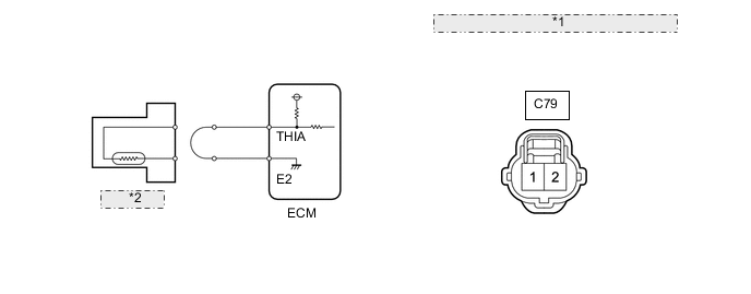
WIRING DIAGRAM
CAUTION / NOTICE / HINT
Note
After replacing the ECM, the new ECM needs registration (See page ) and initialization Click here.
Tech Tips
-
If DTCs relating to different systems are stored, and they share terminal E2 as their ground, check this ground circuit first.
-
Read freeze frame data using the intelligent tester. Freeze frame data records the engine condition when malfunctions are detected. When troubleshooting, freeze frame data can help determine if the vehicle was moving or stationary, if the engine was warmed up or not, and other data from the time the malfunction occurred.
PROCEDURE
-
READ VALUE USING INTELLIGENT TESTER (INTAKE AIR TEMPERATURE [TURBO])
-
Connect the intelligent tester to the DLC3.
-
Turn the ignition switch to ON and turn the tester on.
-
Enter the following menus: Powertrain / Engine / Data List / Intake Air Temp (Turbo).
-
Read the value.
OK Same as air temperature near intake manifold. Result Result Proceed to -40°C (-40°F) A 140°C (284°F) or higher B OK (same as air temperature near intake manifold) C Tech Tips
-
If there is an open circuit, the tester indicates -40°C (-40°F).
-
If there is a short circuit, the tester indicates 140°C (284°F) or more.
-
B 
READ VALUE USING INTELLIGENT TESTER (CHECK FOR SHORT IN WIRE HARNESS) Click here
C
CONFIRM WHETHER MALFUNCTION HAS BEEN SUCCESSFULLY REPAIRED Click here
A 
-
-
READ VALUE USING INTELLIGENT TESTER (CHECK FOR OPEN IN WIRE HARNESS)
-
Disconnect the intake air temperature (IAT) sensor connector.
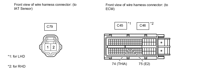
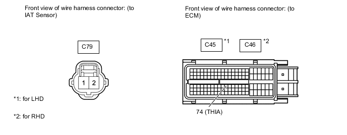
*1 Front view of wire harness connector: (to IAT Sensor) *2 IAT Sensor -
Connect terminals 1 and 2 of the IAT sensor wire harness side connector.
-
Connect the intelligent tester to the DLC3.
-
Turn the ignition switch to ON and turn the tester on.
-
Enter the following menus: Powertrain / Engine / Data List / Intake Air Temp (Turbo).
-
Read the value.
OK 140°C (284°F) or higher
OK
CONFIRM GOOD CONNECTION TO SENSOR. IF OK, REPLACE INTAKE AIR TEMPERATURE SENSOR Click here
NG
-
-
CHECK HARNESS AND CONNECTOR (INTAKE AIR TEMPERATURE SENSOR - ECM)
-
Disconnect the IAT sensor connector.
-
Disconnect the ECM connector.
-
Measure the resistance according to the value(s) in the table below.
Standard Resistance (Check for Open) for LHD Tester Connection Condition Specified Condition C79-2 - C45-74 (THIA) Always Below 1 Ω C79-1 - C45-75 (E2) Always Below 1 Ω for RHD Tester Connection Condition Specified Condition C79-2 - C46-74 (THIA) Always Below 1 Ω C79-1 - C46-75 (E2) Always Below 1 Ω
OK
CONFIRM GOOD CONNECTION TO ECM. IF OK, REPLACE ECM. Click here
NG
REPAIR OR REPLACE HARNESS OR CONNECTOR Click here
-
-
READ VALUE USING INTELLIGENT TESTER (CHECK FOR SHORT IN WIRE HARNESS)
-
*1 IAT Sensor Disconnect the IAT sensor connector.
-
Connect the intelligent tester to the DLC3.
-
Turn the ignition switch to ON and turn the tester on.
-
Enter the following menus: Powertrain / Engine / Data List / Intake Air Temp (Turbo).
-
Read the value.
OK -40°C (-40°F)
OK
REPLACE INTAKE AIR TEMPERATURE SENSOR Click here
NG
-
-
CHECK HARNESS AND CONNECTOR (INTAKE AIR TEMPERATURE SENSOR - ECM)
-
Disconnect the IAT sensor connector.
-
Disconnect the ECM connector.
-
Measure the resistance according to the value(s) in the table below.
Standard Resistance (Check for Short) for LHD Tester Connection Condition Specified Condition C79-2 or C45-74 (THIA) - Body ground Always 10 kΩ or higher for RHD Tester Connection Condition Specified Condition C79-2 or C46-74 (THIA) - Body ground Always 10 kΩ or higher
NG
REPAIR OR REPLACE HARNESS OR CONNECTOR Click here
OK
-
-
REPLACE ECM
-
Replace the ECM Click here.
NEXT
CONFIRM WHETHER MALFUNCTION HAS BEEN SUCCESSFULLY REPAIRED Click here
-
-
CONFIRM GOOD CONNECTION TO SENSOR. IF OK, REPLACE INTAKE AIR TEMPERATURE SENSOR
-
Replace the intake air temperature sensor Click here.
NEXT
CONFIRM WHETHER MALFUNCTION HAS BEEN SUCCESSFULLY REPAIRED Click here
-
-
REPAIR OR REPLACE HARNESS OR CONNECTOR
NEXT
CONFIRM WHETHER MALFUNCTION HAS BEEN SUCCESSFULLY REPAIRED Click here
-
CONFIRM GOOD CONNECTION TO ECM. IF OK, REPLACE ECM.
-
Replace the ECM Click here.
NEXT
CONFIRM WHETHER MALFUNCTION HAS BEEN SUCCESSFULLY REPAIRED Click here
-
-
REPLACE INTAKE AIR TEMPERATURE SENSOR
-
Replace the intake air temperature sensor Click here.
NEXT
-
-
CONFIRM WHETHER MALFUNCTION HAS BEEN SUCCESSFULLY REPAIRED
-
Connect the intelligent tester to the DLC3.
-
Clear the DTCs Click here.
-
Turn the ignition switch off.
-
Turn the ignition switch to ON for 1 second.
-
Enter the following menus: Powertrain / Engine / DTC.
-
Confirm that the DTC is not output again.
NEXT 
END
-