ECD SYSTEM(w/o DPF), Diagnostic DTC:P062D, P062E
| DTC Code | DTC Name |
|---|---|
| P062D | Fuel Injector Driver Circuit Performance Bank1 |
| P062E | Fuel Injector Driver Circuit Performance Bank2 |
DESCRIPTION
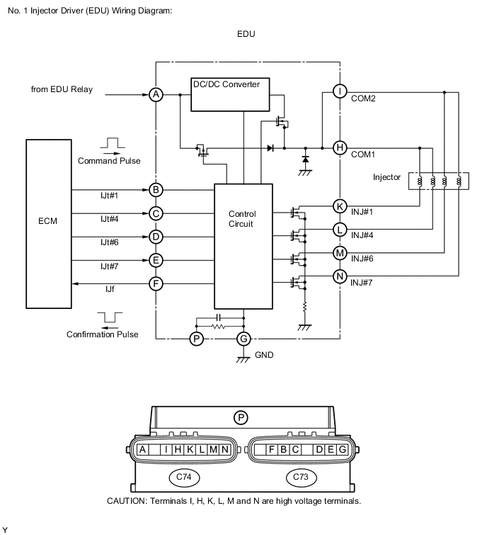
The EDU delivers drive signals to fuel injectors using the DC/DC converter, which provides a high-voltage and quick-charging system.
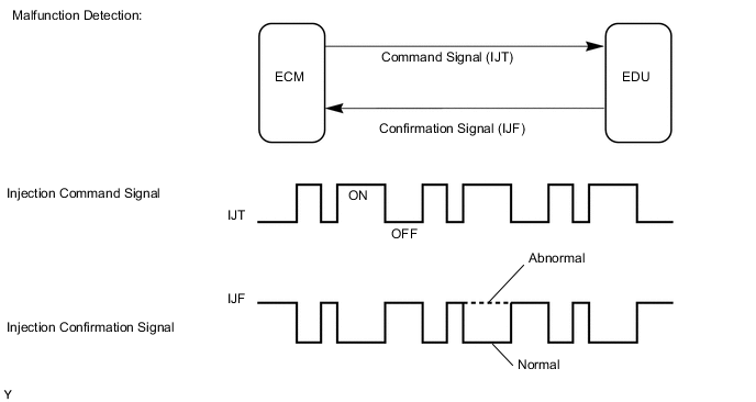
Soon after the EDU receives a fuel injection command (IJT) signal from the ECM, the EDU responds to the command with an injector injection confirmation (IJF) signal when the current is applied to the fuel injector.
| DTC Detection Drive Pattern | DTC Detection Condition | Trouble Area |
|---|---|---|
| Idling for 10 seconds | Open or short in the No. 1 injector driver (EDU) or fuel injector circuit (1 trip detection logic). |
|
| DTC Detection Drive Pattern | DTC Detection Condition | Trouble Area |
|---|---|---|
| Idling for 10 seconds | Open or short in the No. 2 injector driver (EDU) or fuel injector circuit (1 trip detection logic). |
|
MONITOR DESCRIPTION
- P062D, P062E (Open or short in EDU or fuel injector circuit):
The ECM continuously monitors both injection command (IJT) signals and injection confirmation (IJF) signals. This DTC will be stored if the ECM determines that the number of IJT signals and IJF signals are inconsistent.
The fuel injectors are grounded over a Field Effect Transistor (FET) and a serial resistor. This resistor creates a voltage drop, which is monitored by the EDU (injector drive circuit) in relation to the current drawn by the fuel injector. When the fuel injector current becomes too high, the voltage drop over the resistor exceeds a specified level and no IJF signal for that cylinder is sent to the ECM.
After the engine is started, when there is no injection confirmation (IJF) signal from the No. 1 or No. 2 EDU to the ECM even though the ECM sends injection command (IJT) signals to the No. 1 or No. 2 EDU, DTC P062D or DTC P062E is stored.
If this DTC is stored, the ECM enters fail-safe mode and limits engine power or stops the engine. The fail-safe mode continues until the ignition switch is turned off.
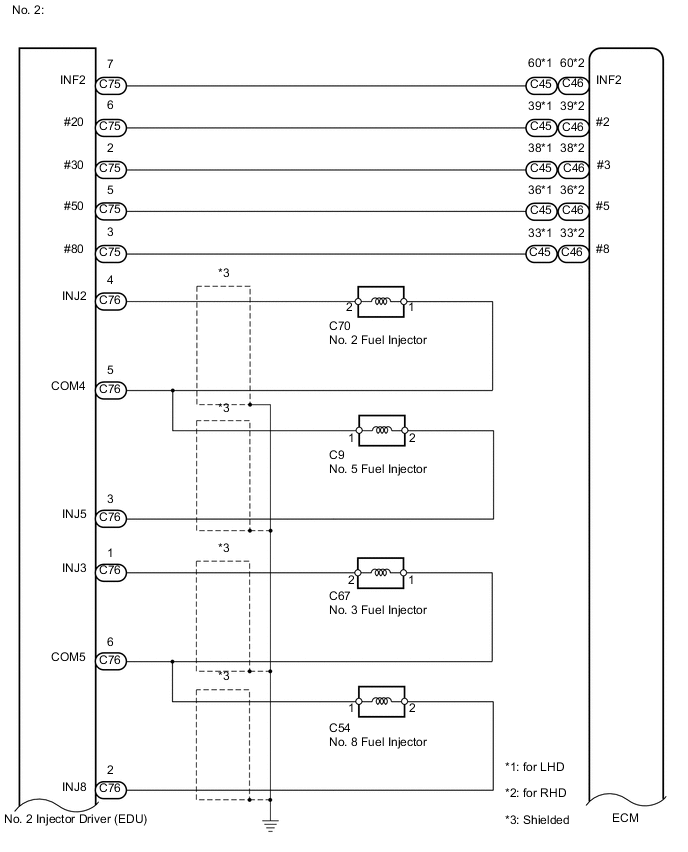
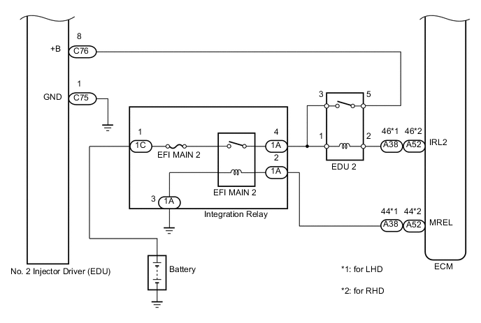
WIRING DIAGRAM
CAUTION / NOTICE / HINT
Note
-
After replacing the ECM, the new ECM needs registration (See page ) and initialization Click here.
-
After replacing a fuel injector, the ECM needs registration Click here.
Tech Tips
Read freeze frame data using the intelligent tester. Freeze frame data records the engine condition when malfunctions are detected. When troubleshooting, freeze frame data can help determine if the vehicle was moving or stationary, if the engine was warmed up or not, and other data from the time the malfunction occurred.
PROCEDURE
-
CHECK TERMINAL VOLTAGE EDU POWER SOURCE
-
Disconnect the No. 1 injector driver (EDU) connectors.
-
Disconnect the No. 2 injector driver (EDU) connectors.
-
Measure the voltage according to the value(s) in the table below.
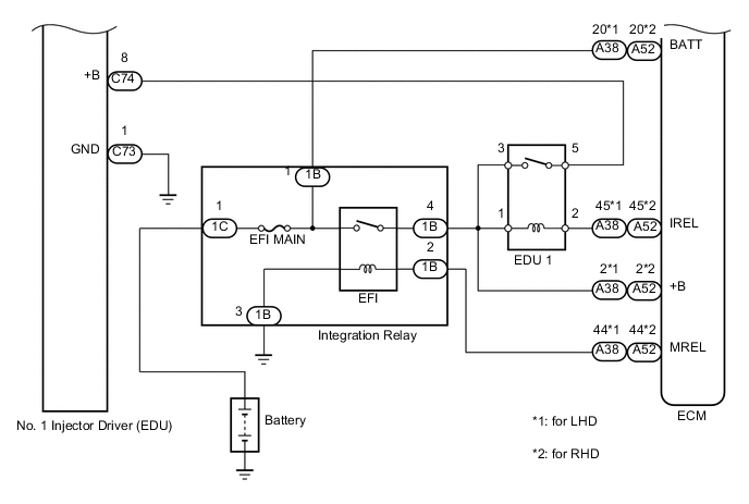
Standard Voltage No. 1 Tester Connection Switch Condition Specified Condition C74-8 (+B) - C73-1 (GND) Ignition switch ON 11 to 14 V No. 2 Tester Connection Switch Condition Specified Condition C76-8 (+B) - C75-1 (GND) Ignition switch ON 11 to 14 V
NG 
GO TO INJECTOR CIRCUIT Click here
OK 
-
-
CHECK HARNESS AND CONNECTOR (FUEL INJECTOR - EDU)

-
Disconnect the fuel injector connectors.
-
Disconnect the No. 1 EDU connector.
-
Measure the resistance according to the value(s) in the table below.
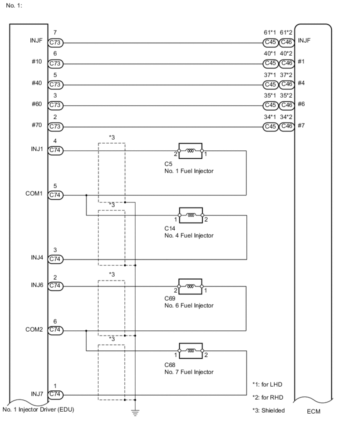
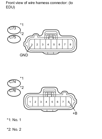
Standard Resistance (Check for Open) No. 1 Tester Connection Condition Specified Condition C5-2 - C74-4 (INJ1) Always Below 1 Ω C14-2 - C74-3 (INJ4) Always Below 1 Ω C69-2 - C74-2 (INJ6) Always Below 1 Ω C68-2 - C74-1 (INJ7) Always Below 1 Ω C5-1 - C74-5 (COM1) Always Below 1 Ω C14-1 - C74-5 (COM1) Always Below 1 Ω C69-1 - C74-6 (COM2) Always Below 1 Ω C68-1 - C74-6 (COM2) Always Below 1 Ω Standard Resistance (Check for Short) No. 1 Tester Connection Condition Specified Condition C5-2 or C74-4 (INJ1) - Body ground Always 10 kΩ or higher C14-2 or C74-3 (INJ4) - Body ground Always 10 kΩ or higher C69-2 or C74-2 (INJ6) - Body ground Always 10 kΩ or higher C68-2 or C74-1 (INJ7) - Body ground Always 10 kΩ or higher C5-1 or C74-5 (COM1) - Body ground Always 10 kΩ or higher C14-1 or C74-5 (COM1) - Body ground Always 10 kΩ or higher C69-1 or C74-6 (COM2) - Body ground Always 10 kΩ or higher C68-1 or C74-6 (COM2) - Body ground Always 10 kΩ or higher 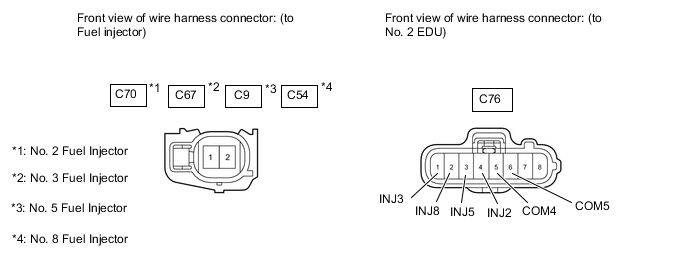
-
Disconnect the fuel injector connectors.
-
Disconnect the No. 2 EDU connector.
-
Measure the resistance according to the value(s) in the table below.
Standard Resistance (Check for Open) No. 2 Tester Connection Condition Specified Condition C70-2 - C76-4 (INJ2) Always Below 1 Ω C9-2 - C76-3 (INJ5) Always Below 1 Ω C67-2 - C76-1 (INJ3) Always Below 1 Ω C54-2 - C76-2 (INJ8) Always Below 1 Ω C70-1 - C76-5 (COM4) Always Below 1 Ω C9-1 - C76-5 (COM4) Always Below 1 Ω C67-1 - C76-6 (COM5) Always Below 1 Ω C54-1 - C76-6 (COM5) Always Below 1 Ω Standard Resistance (Check for Short) No. 2 Tester Connection Condition Specified Condition C70-2 or C76-4 (INJ2) - Body ground Always 10 kΩ or higher C9-2 or C76-3 (INJ5) - Body ground Always 10 kΩ or higher C67-2 or C76-1 (INJ3) - Body ground Always 10 kΩ or higher C54-2 or C76-2 (INJ8) - Body ground Always 10 kΩ or higher C70-1 or C76-5 (COM4) - Body ground Always 10 kΩ or higher C9-1 or C76-5 (COM4) - Body ground Always 10 kΩ or higher C67-1 or C76-6 (COM5) - Body ground Always 10 kΩ or higher C54-1 or C76-6 (COM5) - Body ground Always 10 kΩ or higher
NG
REPAIR OR REPLACE HARNESS OR CONNECTOR Click here
OK
-
-
CHECK HARNESS AND CONNECTOR (EDU - ECM)
-
Disconnect the No. 1 EDU connector.
-
Disconnect the ECM connector.
-
Measure the resistance according to the value(s) in the table below.
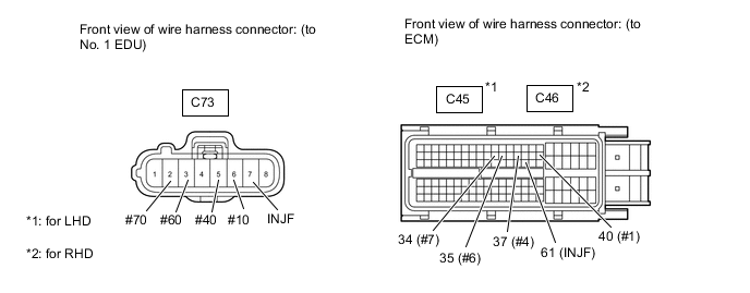
Standard Resistance (Check for Open) No. 1 (for LHD) Tester Connection Condition Specified Condition C73-6 (#10) - C45-40 (#1) Always Below 1 Ω C73-5 (#40) - C45-37 (#4) Always Below 1 Ω C73-3 (#60) - C45-35 (#6) Always Below 1 Ω C73-2 (#70) - C45-34 (#7) Always Below 1 Ω C73-7 (INJF) - C45-61 (INJF) Always Below 1 Ω No. 1 (for RHD) Tester Connection Condition Specified Condition C73-6 (#10) - C46-40 (#1) Always Below 1 Ω C73-5 (#40) - C46-37 (#4) Always Below 1 Ω C73-3 (#60) - C46-35 (#6) Always Below 1 Ω C73-2 (#70) - C46-34 (#7) Always Below 1 Ω C73-7 (INJF) - C46-61 (INJF) Always Below 1 Ω Standard Resistance (Check for Short) No. 1 (for LHD) Tester Connection Condition Specified Condition C73-6 (#10) or C45-40 (#1) - Body ground Always 10 kΩ or higher C73-5 (#40) or C45-37 (#4) - Body ground Always 10 kΩ or higher C73-3 (#60) or C45-35 (#6) - Body ground Always 10 kΩ or higher C73-2 (#70) or C45-34 (#7) - Body ground Always 10 kΩ or higher C73-7 (INJF) or C45-61 (INJF) - Body ground Always 10 kΩ or higher No. 1 (for RHD) Tester Connection Condition Specified Condition C73-6 (#10) or C46-40 (#1) - Body ground Always 10 kΩ or higher C73-5 (#40) or C46-37 (#4) - Body ground Always 10 kΩ or higher C73-3 (#60) or C46-35 (#6) - Body ground Always 10 kΩ or higher C73-2 (#70) or C46-34 (#7) - Body ground Always 10 kΩ or higher C73-7 (INJF) or C46-61 (INJF) - Body ground Always 10 kΩ or higher -
Disconnect the No. 2 EDU connector.
-
Disconnect the ECM connector.
-
Measure the resistance according to the value(s) in the table below.
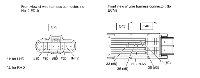
Standard Resistance (Check for Open) No. 2 (for LHD) Tester Connection Condition Specified Condition C75-6 (#20) - C45-39 (#2) Always Below 1 Ω C75-2 (#30) - C45-38 (#3) Always Below 1 Ω C75-5 (#50) - C45-36 (#5) Always Below 1 Ω C75-3 (#80) - C45-33 (#8) Always Below 1 Ω C75-7 (INF2) - C45-60 (INF2) Always Below 1 Ω No. 2 (for RHD) Tester Connection Condition Specified Condition C75-6 (#20) - C46-39 (#2) Always Below 1 Ω C75-2 (#30) - C46-38 (#3) Always Below 1 Ω C75-5 (#50) - C46-36 (#5) Always Below 1 Ω C75-3 (#80) - C46-33 (#8) Always Below 1 Ω C75-7 (INF2) - C46-60 (INF2) Always Below 1 Ω Standard Resistance (Check for Short) No. 2 (for LHD) Tester Connection Condition Specified Condition C75-6 (#20) or C45-39 (#2) - Body ground Always 10 kΩ or higher C75-2 (#30) or C45-38 (#3) - Body ground Always 10 kΩ or higher C75-5 (#50) or C45-36 (#5) - Body ground Always 10 kΩ or higher C75-3 (#80) or C45-33 (#8) - Body ground Always 10 kΩ or higher C75-7 (INF2) or C45-60 (INF2) - Body ground Always 10 kΩ or higher No. 2 (for RHD) Tester Connection Condition Specified Condition C75-6 (#20) or C46-39 (#2) - Body ground Always 10 kΩ or higher C75-2 (#30) or C46-38 (#3) - Body ground Always 10 kΩ or higher C75-5 (#50) or C46-36 (#5) - Body ground Always 10 kΩ or higher C75-3 (#80) or C46-33 (#8) - Body ground Always 10 kΩ or higher C75-7 (INF2) or C46-60 (INF2) - Body ground Always 10 kΩ or higher
NG
REPAIR OR REPLACE HARNESS OR CONNECTOR Click here
OK
-
-
INSPECT FUEL INJECTOR (RESISTANCE)
-
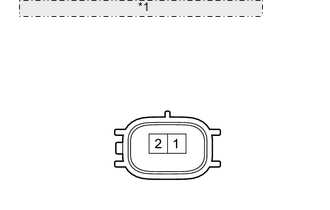
*1 Component without harness connected: (Fuel injector) Disconnect the fuel injector connectors.
-
Measure the resistance according to the value(s) in the table below.
Standard Resistance Tester Connection Condition Specified Condition 1 - 2 20°C (68°F) 0.85 to 1.05 Ω
NG
REPLACE FUEL INJECTOR Click here
OK
-
-
INSPECT INJECTOR DRIVER (No. 1 and No. 2)
-
Interchange the No. 1 and No. 2 EDU connectors.
-
Connect the intelligent tester to the DLC3.
-
Turn the ignition switch to ON and turn the tester on.
-
Clear the DTCs Click here.
Note
Before clearing the DTCs, write them down.
-
Start the engine.
-
Enter the following menus: Powertrain / Engine / DTC.
-
Read the DTCs.
Result Result Proceed to DTCs do not change A DTCs change (change in malfunctioning cylinder or EDU code) B
B
REPLACE INJECTOR DRIVER (No. 1 or No. 2) Click here
A
-
-
REPLACE ECM
-
Replace the ECM Click here.
NEXT
CONFIRM WHETHER MALFUNCTION HAS BEEN SUCCESSFULLY REPAIRED Click here
-
-
GO TO INJECTOR CIRCUIT
-
Go to the injector circuit Click here.
NEXT
CONFIRM WHETHER MALFUNCTION HAS BEEN SUCCESSFULLY REPAIRED Click here
-
-
REPLACE INJECTOR DRIVER (No. 1 or No. 2)
-
Replace the injector driver (No. 1 or No. 2) Click here.
NEXT
CONFIRM WHETHER MALFUNCTION HAS BEEN SUCCESSFULLY REPAIRED Click here
-
-
REPLACE FUEL INJECTOR
-
Replace the fuel injector Click here.
NEXT
CONFIRM WHETHER MALFUNCTION HAS BEEN SUCCESSFULLY REPAIRED Click here
-
-
REPAIR OR REPLACE HARNESS OR CONNECTOR
NEXT
-
CONFIRM WHETHER MALFUNCTION HAS BEEN SUCCESSFULLY REPAIRED
-
Connect the intelligent tester to the DLC3.
-
Clear the DTCs Click here.
-
Turn the ignition switch off.
-
Start the engine and idle it for 10 seconds.
-
Enter the following menus: Powertrain / Engine / DTC.
-
Confirm that the DTC is not output again.
NEXT 
END
-