ECD SYSTEM(w/o DPF) Active Control Engine Mount System
DESCRIPTION
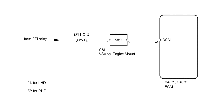
The Active Control Engine Mount (ACM) system decreases engine vibration at low engine speed using the VSV for engine mount. The VSV is controlled by a pulse signal transmitted to the VSV from the ECM. The frequency of this pulse signal is matched to the engine speed to decrease engine vibration.
WIRING DIAGRAM
CAUTION / NOTICE / HINT
Note
After replacing the ECM, the new ECM needs registration (See page ) and initialization Click here.
PROCEDURE
-
PERFORM ACTIVE TEST USING INTELLIGENT TESTER
-
Warm up the engine.
-
Connect the intelligent tester to the DLC3.
-
Move the shift lever to N or P.
-
Enter the following menus: Powertrain / Engine / Active Test / Control the ACM Inhibit.
-
Hold the top part of the steering wheel, and turn the Active Test from OFF to ON. Check the engine vibration.
Result Engine Vibration Proceed to Increases A Does not increase B
A 
CHECK FOR INTERMITTENT PROBLEMS Click here
B 
-
-
CHECK VACUUM
-
Check if the vacuum hose cap is missing, if the hose is damaged, and if the air and vacuum hoses have looseness, disconnection or blockage.
OK Vacuum hose cap is not missing and hoses are normal.
NG
REPLACE VACUUM HOSE
OK
-
-
INSPECT VSV FOR ENGINE MOUNT
-
Inspect the VSV for engine mount Click here.
NG
REPLACE VSV FOR ENGINE MOUNT Click here
OK
-
-
CHECK HARNESS AND CONNECTOR (VSV FOR ENGINE MOUNT - ECM, EFI NO. 2 FUSE - VSV FOR ENGINE MOUNT)
-
Disconnect the VSV for engine mount connector.
-
Disconnect the ECM connector.
-
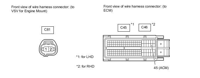
Measure the resistance according to the value(s) in the table below.
Standard Resistance (Check for Open) for LHD Tester Connection Condition Specified Condition C81-2 - C45-45 (ACM) Always Below 1 Ω for RHD Tester Connection Condition Specified Condition C81-2 - C46-45 (ACM) Always Below 1 Ω Standard Resistance (Check for Short) for LHD Tester Connection Condition Specified Condition C81-2 or C45-45 (ACM) - Body ground Always 10 kΩ or higher for RHD Tester Connection Condition Specified Condition C81-2 or C46-45 (ACM) - Body ground Always 10 kΩ or higher -
Remove the EFI NO. 2 fuse from the engine room relay block.
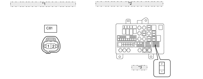
*1 Front view of wire harness connector: (to VSV for Engine Mount) *2 Front view of wire harness connector: (to Engine Room Relay Block) *3 EFI NO. 2 -
Measure the resistance according to the value(s) in the table below.
Standard Resistance Tester Connection Condition Specified Condition EFI NO. 2 fuse (2) - C81-1 Always Below 1 Ω
NG
REPAIR OR REPLACE HARNESS OR CONNECTOR
OK
-
-
INSPECT ENGINE MOUNTING INSULATOR FRONT
-
Inspect the engine mounting insulator front Click here.
OK
REPLACE ECM Click here
NG
REPLACE ENGINE MOUNTING INSULATOR FRONT Click here
-