ECD SYSTEM(w/o DPF), Diagnostic DTC:P0100, P0102, P0103
| DTC Code | DTC Name |
|---|---|
| P0100 | Mass or Volume Air Flow Circuit |
| P0102 | Mass or Volume Air Flow Circuit Low Input |
| P0103 | Mass or Volume Air Flow Circuit High Input |
DESCRIPTION
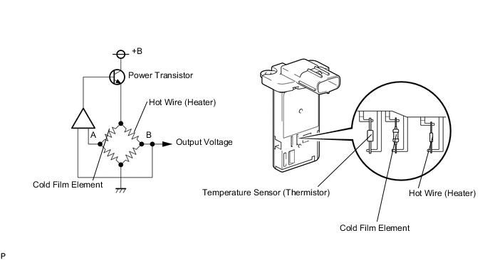
The Mass Air Flow (MAF) meter uses a platinum hot wire. The mass air flow meter consists of a platinum hot wire, a temperature sensor and a control circuit installed in a plastic housing. The mass air flow meter hot wire and temperature sensor (located in the intake air by-pass of the housing) detect changes in the intake air temperature.
The hot wire is maintained at the predetermined temperature by controlling the current flow through the hot wire. This current flow is then used as the output voltage of the mass air flow meter.
The circuit is constructed so that the platinum hot wire and temperature sensor provide a bridge circuit, with the power transistor controlled so that the potential of A and B remains equal to maintain the predetermined temperature.
| DTC Detection Drive Pattern | DTC Detection Condition | Trouble Area |
|---|---|---|
| Ignition switch ON for 3 seconds | Mass air flow (MAF) meter voltage is 0.2 V or less, or 4.9 V or more with the engine speed at 4000 rpm or less for 3 seconds (1 trip detection logic). |
|
| DTC Detection Drive Pattern | DTC Detection Condition | Trouble Area |
|---|---|---|
| Ignition switch ON for 3 seconds | MAF meter voltage is 0.2 V or less with the engine speed at 4000 rpm or less for 3 seconds (1 trip detection logic). |
|
| DTC Detection Drive Pattern | DTC Detection Condition | Trouble Area |
|---|---|---|
| Ignition switch ON for 3 seconds | MAF meter voltage is 4.9 V or more with the engine speed at 4000 rpm or less for 3 seconds (1 trip detection logic). |
|
| DTC No. | Data List |
|---|---|
| P0100 | MAF |
| P0102 | |
| P0103 |
Tech Tips
-
If DTC P0100, and/or P0102 is stored, the following symptoms may appear (as the ECU mistakenly determines that there is less air than the actual intake air amount, EGR is decreased to match the target EGR):
-
Combustion noise worsens
-
If DTC P0100, and/or P0103 is stored, the following symptoms may appear (as the ECU mistakenly determines that there is more air than the actual intake air amount, EGR is increased to match the target EGR):
-
Misfire
-
White smoke
-
Black smoke
-
After confirming DTC P0100, P0102 or P0103, check the mass air flow ratio by entering the following menus: Powertrain / Engine / Data List / MAF.
Reference: Air Flow Value (g/sec.) Malfunction Approximately 0.0
-
Open in mass air flow meter power source circuit
-
Open or short in VG circuit
174.0 or more Open in EVG circuit -
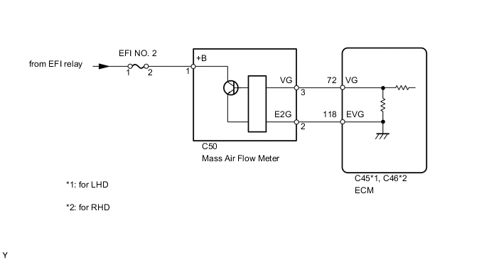
WIRING DIAGRAM
CAUTION / NOTICE / HINT
Note
After replacing the ECM, the new ECM needs registration (See page ) and initialization Click here.
Tech Tips
Read freeze frame data using the intelligent tester. Freeze frame data records the engine condition when malfunctions are detected. When troubleshooting, freeze frame data can help determine if the vehicle was moving or stationary, if the engine was warmed up or not, and other data from the time the malfunction occurred.
PROCEDURE
-
READ VALUE USING INTELLIGENT TESTER (MASS AIR FLOW RATE)
-
Connect the intelligent tester to the DLC3.
-
Start the engine and turn the tester on.
-
Enter the following menus: Powertrain / Engine / Data List / MAF.
-
Read the value.
Result Result Proceed to 0.0 A 174.0 or more B Between 1 and 173.0* C Tech Tips
*: The value should change when the throttle valve is opened or closed.
B 
CHECK HARNESS AND CONNECTOR (SENSOR GROUND) Click here
C
CONFIRM WHETHER MALFUNCTION HAS BEEN SUCCESSFULLY REPAIRED Click here
A 
-
-
INSPECT MASS AIR FLOW METER (POWER SOURCE CIRCUIT)
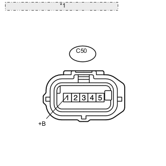
*1 Front view of wire harness connector: (to Mass Air Flow Meter)
-
Disconnect the mass air flow meter connector.
-
Measure the voltage according to the value(s) in the table below.
Standard Voltage Tester Connection Switch Condition Specified Condition C50-1 (+B) - Body ground Ignition switch ON 11 to 14 V
NG
INSPECT FUSE (EFI NO. 2) Click here
OK
-
-
INSPECT MASS AIR FLOW METER
-
Inspect the mass air flow meter Click here.
NG
REPLACE MASS AIR FLOW METER Click here
OK
-
-
CHECK HARNESS AND CONNECTOR (MASS AIR FLOW METER - ECM)
-
Disconnect the mass air flow meter connector.
-
Disconnect the ECM connector.
-
Measure the resistance according to the value(s) in the table below.
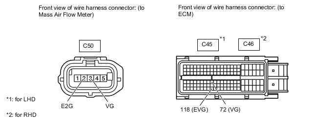
Standard Resistance (Check for Open) for LHD Tester Connection Condition Specified Condition C50-3 (VG) - C45-72 (VG) Always Below 1 Ω C50-2 (E2G) - C45-118 (EVG) Always Below 1 Ω for RHD Tester Connection Condition Specified Condition C50-3 (VG) - C46-72 (VG) Always Below 1 Ω C50-2 (E2G) - C46-118 (EVG) Always Below 1 Ω Standard Resistance (Check for Short) for LHD Tester Connection Condition Specified Condition C50-3 (VG) or C45-72 (VG) - Body ground Always 10 kΩ or higher for RHD Tester Connection Condition Specified Condition C50-3 (VG) or C46-72 (VG) - Body ground Always 10 kΩ or higher
OK
REPLACE ECM Click here
NG
REPAIR OR REPLACE HARNESS OR CONNECTOR Click here
-
-
INSPECT FUSE (EFI NO. 2)
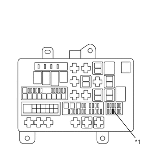
Engine Room Relay Block *1 EFI NO. 2
-
Remove the EFI NO. 2 fuse from the engine room relay block.
-
Measure the resistance according to the value(s) in the table below.
Standard Resistance Tester Connection Condition Specified Condition EFI NO. 2 fuse Always Below 1 Ω
NG
CHECK FOR SHORTS IN ALL HARNESSES AND CONNECTORS CONNECTED TO FUSE AND REPLACE FUSE Click here
OK
-
-
CHECK HARNESS AND CONNECTOR (MASS AIR FLOW METER - ENGINE ROOM RELAY BLOCK)
-
Disconnect the mass air flow meter connector.
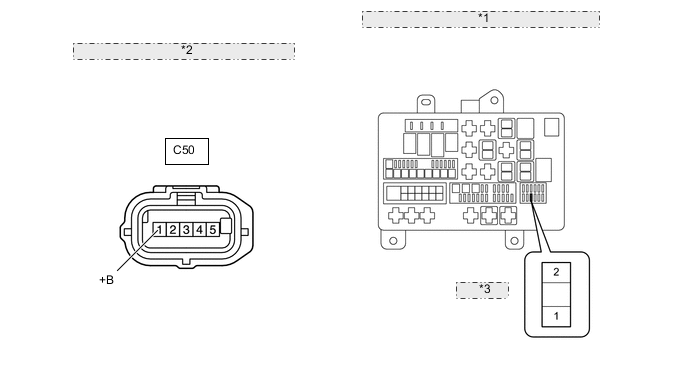
*1 Component without harness connected: (Engine Room Relay Block) *2 Front view of wire harness connector: (to Mass Air Flow Meter) *3 EFI NO. 2 -
Remove the EFI NO. 2 fuse from the engine room relay block.
-
Measure the resistance according to the value(s) in the table below.
Standard Resistance (Check for Open) Tester Connection Condition Specified Condition C50-1 (+B) - EFI NO. 2 fuse (2) Always Below 1 Ω Standard Resistance (Check for Short) Tester Connection Condition Specified Condition C50-1 (+B) or EFI NO. 2 fuse (2) - Body ground Always 10 kΩ or higher
NG
REPAIR OR REPLACE HARNESS OR CONNECTOR Click here
OK
-
-
CHECK HARNESS AND CONNECTOR (ENGINE ROOM RELAY BLOCK)
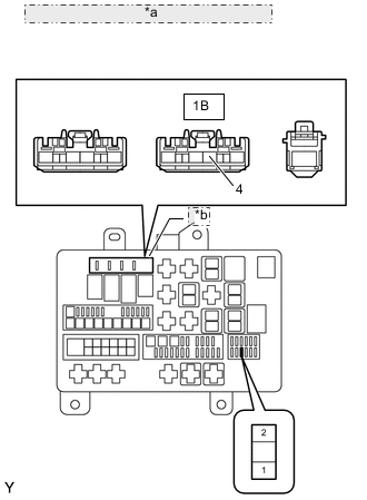
*a Front view of wire harness connector: (to Engine Room Relay Block) *b Integration Relay
-
Remove the EFI NO. 2 fuse from the engine room relay block.
-
Remove the integration relay from the engine room relay block.
-
Measure the resistance according to the value(s) in the table below.
Standard Resistance (Check for Open) Tester Connection Condition Specified Condition EFI NO. 2 fuse (1) - 1B-4 Always Below 1 Ω Standard Resistance (Check for Short) Tester Connection Condition Specified Condition EFI NO. 2 fuse (1) or 1B-4 - Body ground Always 10 kΩ or higher
OK
CHECK ECM POWER SOURCE CIRCUIT Click here
NG
REPAIR OR REPLACE HARNESS OR CONNECTOR Click here
-
-
CHECK HARNESS AND CONNECTOR (SENSOR GROUND)
-
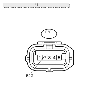
*1 Front view of wire harness connector: (to Mass Air Flow Meter) Disconnect the mass air flow meter connector.
-
Measure the resistance according to the value(s) in the table below.
Standard Resistance (Check for Open) Tester Connection Condition Specified Condition C50-2 (E2G) - Body ground Always Below 1 Ω
OK
REPLACE MASS AIR FLOW METER Click here
NG
-
-
CHECK HARNESS AND CONNECTOR (MASS AIR FLOW METER - ECM)
-
Disconnect the mass air flow meter connector.
-
Disconnect the ECM connector.
-
Measure the resistance according to the value(s) in the table below.
Standard Resistance (Check for Open) for LHD Tester Connection Condition Specified Condition C50-3 (VG) - C45-72 (VG) Always Below 1 Ω C50-2 (E2G) - C45-118 (EVG) Always Below 1 Ω for RHD Tester Connection Condition Specified Condition C50-3 (VG) - C46-72 (VG) Always Below 1 Ω C50-2 (E2G) - C46-118 (EVG) Always Below 1 Ω Standard Resistance (Check for Short) for LHD Tester Connection Condition Specified Condition C50-3 (VG) or C45-72 (VG) - Body ground Always 10 kΩ or higher for RHD Tester Connection Condition Specified Condition C50-3 (VG) or C46-72 (VG) - Body ground Always 10 kΩ or higher
NG
REPAIR OR REPLACE HARNESS OR CONNECTOR Click here
OK
-
-
REPLACE ECM
-
Replace the ECM Click here.
NEXT
CONFIRM WHETHER MALFUNCTION HAS BEEN SUCCESSFULLY REPAIRED Click here
-
-
REPLACE MASS AIR FLOW METER
-
Replace the mass air flow meter Click here.
NEXT
CONFIRM WHETHER MALFUNCTION HAS BEEN SUCCESSFULLY REPAIRED Click here
-
-
REPAIR OR REPLACE HARNESS OR CONNECTOR
NEXT
CONFIRM WHETHER MALFUNCTION HAS BEEN SUCCESSFULLY REPAIRED Click here
-
CHECK FOR SHORTS IN ALL HARNESSES AND CONNECTORS CONNECTED TO FUSE AND REPLACE FUSE
NEXT
CONFIRM WHETHER MALFUNCTION HAS BEEN SUCCESSFULLY REPAIRED Click here
-
CHECK ECM POWER SOURCE CIRCUIT
-
Check the ECM power source circuit Click here.
NEXT
-
-
CONFIRM WHETHER MALFUNCTION HAS BEEN SUCCESSFULLY REPAIRED
-
Connect the intelligent tester to the DLC3.
-
Clear the DTCs Click here.
-
Turn the ignition switch off.
-
Turn the ignition switch to ON for 3 seconds
-
Enter the following menus: Powertrain / Engine / DTC.
-
Confirm that the DTC is not output again.
NEXT 
END
-