ECD SYSTEM(w/o DPF), Diagnostic DTC:P0400, P1248
| DTC Code | DTC Name |
|---|---|
| P0400 | Exhaust Gas Recirculation Flow |
| P1248 | Exhaust Gas Recirculation Flow Bank 2 |
DESCRIPTION
The EGR system recirculates exhaust gases. The recirculated gas mingles with the intake air so that the EGR system can slow combustion speed and keep the combustion temperature down. This helps reduce NOx emissions.
In order to increase EGR circulation efficiency, the ECM adjusts the lift amount of the EGR valve and the throttle valve angle.
| DTC Detection Drive Pattern | DTC Detection Condition | Trouble Area |
|---|---|---|
| After warming up engine and idling for 60 seconds, maintain engine speed at 2500 rpm for 40 seconds, drive vehicle and perform engine break deceleration by fully closing accelerator when engine speed is 2000 rpm or more | The target and actual positions of the No. 1 EGR valve assembly are different for 30 seconds or more (1 trip detection logic). |
|
| DTC Detection Drive Pattern | DTC Detection Condition | Trouble Area |
|---|---|---|
| Decelerate from a speed of 50 km/h (80 mph) or more (release accelerator pedal for approximately 5 seconds) | Mass air flow rate is not changed when turning on the electric EGR control valve while decelerating (2 trip detection logic). |
|
| DTC No. | Data List |
|---|---|
| P0400 (No. 1 EGR valve malfunction) |
|
| P1248 (No. 2 EGR valve malfunction) |
|
| P0400 (Flow malfunction) |
Tech Tips
If DTC P0400 and/or P1238 is stored, the following symptoms may appear:
-
Stuck closed malfunction
-
Intake booming noise
-
Slight combustion noise
-
Stuck open malfunction
-
Black smoke
-
Lack of power
-
Vibration at engine stop
-
Hesitation
MONITOR DESCRIPTION
-
When the target and actual positions of the EGR valve are different, the ECM interprets this as a malfunction of the EGR valve and illuminates the MIL (1 trip detection logic).
-
If the electric EGR control valve is forcibly operated but the intake air amount does not vary, the ECM determines that the electric EGR control valve is malfunctioning. The ECM then illuminates the MIL (2 trip detection logic).
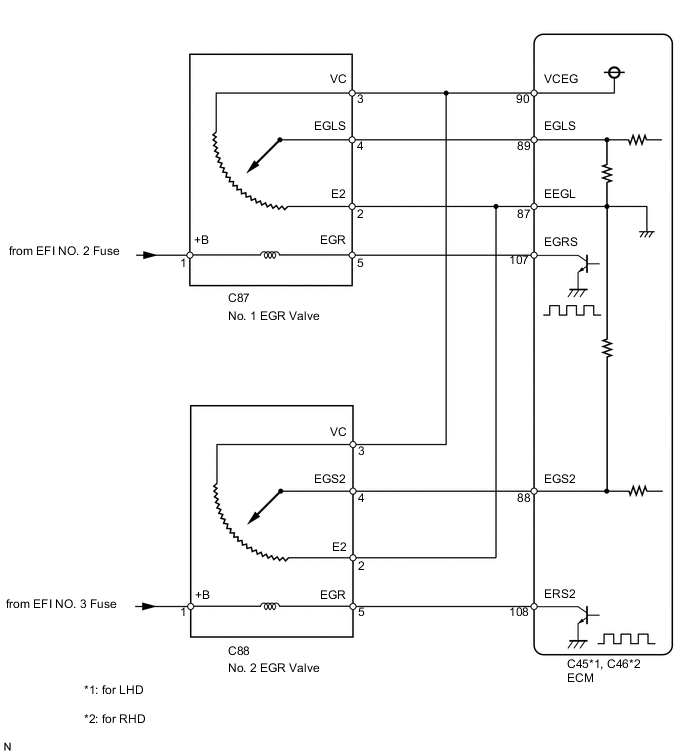
WIRING DIAGRAM
CAUTION / NOTICE / HINT
Note
After replacing the ECM, the new ECM needs registration (See page ) and initialization Click here.
Tech Tips
-
The Data List item Actual EGR Valve Pos. changes to follow Target EGR Position. When the ignition switch is ON (engine stopped), the EGR valve is fully closed (Actual EGR Valve Pos. = 0), and when idling, the EGR valve is open partway (neither fully closed nor fully open).
-
Read freeze frame data using the intelligent tester. Freeze frame data records the engine condition when malfunctions are detected. When troubleshooting, freeze frame data can help determine if the vehicle was moving or stationary, if the engine was warmed up or not, and other data from the time the malfunction occurred.
PROCEDURE
-
CHECK OTHER DTC OUTPUT (IN ADDITION TO DTC P0400, P1248)
-
Connect the intelligent tester to the DLC3.
-
Turn the ignition switch to ON and turn the tester on.
-
Enter the following menus: Powertrain / Engine / DTC.
-
Read the DTCs.
Result Result Proceed to P0400 and/or P1248 are output A P0400, P1248 and other DTCs are output B Tech Tips
If codes other than P0400 and P1248 are output, perform troubleshooting for those DTCs first.
B 
GO TO DTC CHART Click here
A 
-
-
PERFORM ACTIVE TEST USING INTELLIGENT TESTER (CONTROL THE EGR STEP POSITION)
-
Connect the intelligent tester to the DLC3.
-
Turn the ignition switch to ON and turn the tester on.
-
Enter the following menus: Powertrain / Engine / Active Test / Control the EGR Step Position or Control the EGR Step Position #2 / Data List / Actual EGR Valve Pos. or Actual EGR Valve Pos. #2.
-
When changing the Active Test value from 0 to 100%, check that Actual EGR Valve Pos. or Actual EGR Valve Pos. #2 smoothly changes to the set opening angle.
OK Value smoothly changes to within +/-10% of set opening angle. Tech Tips
-
EGR valve closed: Actual EGR Valve Pos. is 0%
-
EGR valve open: Actual EGR Valve Pos. is 94.9%
-
NG 
INSPECT EGR VALVE ASSEMBLY (POWER SOURCE) Click here
OK
-
-
READ VALUE USING INTELLIGENT TESTER (EGR VALVE LEARNING VALUE)
-
Connect the intelligent tester to the DLC3.
-
Turn the ignition switch from ON to off, and wait 5 seconds. Then turn the ignition switch to ON and the tester on.
-
Enter the following menus: Powertrain / Engine / Data List / EGR Close Learn Val. or EGR Close Lrn. Val. #2, and EGR Lift Sensor Volt % or EGR Lift Sensor Volt % #2.
-
Check the value.
OK Tester Display Standard value EGR Close Learn Val. 3.5 to 4.5 V EGR Close Lrn. Val. #2 3.5 to 4.5 V EGR Lift Sensor Volt % 70 to 90% EGR Lift Sensor Volt % #2 70 to 90% Tech Tips
-
When EGR Close Lrn. Status is OFF (learning is incomplete) or EGR Close Lrn. Value is 3.5 V (lower limit), there is foreign matter stuck in the valve.
-
The median value of EGR Close Lrn. Value is 4.0 V.
-
NG
REMOVE FOREIGN OBJECT AND CLEAN EGR VALVE (No. 1 or No. 2) Click here
OK
-
-
CHECK FOR DEPOSIT (EGR PASSAGE)
-
Check for any deposits.
OK No deposits.
NG
REPAIR OR REPLACE MALFUNCTIONING PARTS, COMPONENT AND AREA Click here
OK
-
-
CHECK FOR EXHAUST GAS LEAKS
-
Check for exhaust gas leaks.
OK No leaks.
OK
CHECK WHETHER DTC OUTPUT RECURS Click here
NG
REPAIR EXHAUST GAS LEAKAGE POINT Click here
-
-
INSPECT EGR VALVE ASSEMBLY (POWER SOURCE)
-
Disconnect the EGR valve connector.
-
Measure the voltage according to the value(s) in the table below.
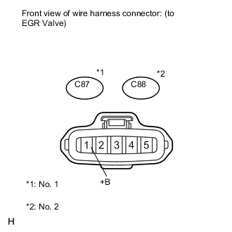
Standard Voltage No. 1 Tester Connection Switch Condition Specified Condition C87-1 (+B) - Body ground Ignition switch ON 11 to 14 V No. 2 Tester Connection Switch Condition Specified Condition C88-1 (+B) - Body ground Ignition switch ON 11 to 14 V
NG
REPAIR OR REPLACE HARNESS OR CONNECTOR (BATTERY - EGR VALVE CONNECTOR) Click here
OK
-
-
CHECK HARNESS AND CONNECTOR (EGR VALVE ASSEMBLY - ECM)
-
Disconnect the EGR valve connector.
-
Disconnect the ECM connector.
-
Measure the resistance according to the value(s) in the table below.
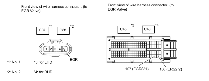
Standard Resistance (Check for Open) No. 1 (LHD) Tester Connection Condition Specified Condition C87-5 (EGR) - C45-107 (EGRS) Always Below 1 Ω No. 2 (LHD) Tester Connection Condition Specified Condition C88-5 (EGR) - C45-108 (ERS2) Always Below 1 Ω No. 1 (RHD) Tester Connection Condition Specified Condition C87-5 (EGR) - C46-107 (EGRS) Always Below 1 Ω No. 2 (RHD) Tester Connection Condition Specified Condition C88-5 (EGR) - C46-108 (ERS2) Always Below 1 Ω Standard Resistance (Check for Short) No. 1 (LHD) Tester Connection Condition Specified Condition C87-5 (EGR) or C45-107 (EGRS) - Body ground Always 10 kΩ or higher No. 2 (LHD) Tester Connection Condition Specified Condition C88-5 (EGR) or C45-108 (ERS2) - Body ground Always 10 kΩ or higher No. 1 (RHD) Tester Connection Condition Specified Condition C87-5 (EGR) or C46-107 (EGRS) - Body ground Always 10 kΩ or higher No. 2 (RHD) Tester Connection Condition Specified Condition C88-5 (EGR) or C46-108 (ERS2) - Body ground Always 10 kΩ or higher
NG
REPAIR OR REPLACE HARNESS OR CONNECTOR Click here
OK
-
-
REPLACE EGR VALVE ASSEMBLY (No. 1 or No. 2)
-
Replace the EGR valve assembly (No. 1 or No. 2) Click here.
NEXT
-
-
CHECK WHETHER DTC OUTPUT RECURS
-
Clear the DTCs Click here.
-
Connect the intelligent tester to the DLC3.
-
Turn the ignition switch to ON and turn the tester on.
-
Start the engine and warm it up.
-
Switch the ECM from normal mode to check mode using the tester Click here.
-
After warming up the engine and idling for 60 seconds, maintain the engine speed at 2500 rpm for 40 seconds, decelerate from a speed of 50 km/h (80 mph) or more (release accelerator pedal for approximately 5 seconds).
-
Confirm that the DTC is not output again.
Tech Tips
Perform the following procedure using the tester to determine whether or not the DTC judgment has been carried out.
-
Enter the following menus: Powertrain / Engine / Utility / All Readiness.
-
Input DTC P0400 and/or P1248.
-
Check that STATUS is NORMAL. If STATUS is INCOMPLETE or UNKNOWN, after warming up the engine and idling for 60 seconds, maintain the engine speed at 2500 rpm for 40 seconds, decelerate from a speed of 50 km/h (80 mph) or more (release accelerator pedal for approximately 5 seconds).
Result Result Proceed to NORMAL A ABNORMAL B
-
A
END
B
REPLACE ECM Click here
-
-
REMOVE FOREIGN OBJECT AND CLEAN EGR VALVE (No. 1 or No. 2)
NEXT
CONFIRM WHETHER MALFUNCTION HAS BEEN SUCCESSFULLY REPAIRED Click here
-
REPAIR OR REPLACE MALFUNCTIONING PARTS, COMPONENT AND AREA
NEXT
CONFIRM WHETHER MALFUNCTION HAS BEEN SUCCESSFULLY REPAIRED Click here
-
REPAIR EXHAUST GAS LEAKAGE POINT
NEXT
CONFIRM WHETHER MALFUNCTION HAS BEEN SUCCESSFULLY REPAIRED Click here
-
REPAIR OR REPLACE HARNESS OR CONNECTOR (BATTERY - EGR VALVE CONNECTOR)
NEXT
CONFIRM WHETHER MALFUNCTION HAS BEEN SUCCESSFULLY REPAIRED Click here
-
REPAIR OR REPLACE HARNESS OR CONNECTOR
NEXT
CONFIRM WHETHER MALFUNCTION HAS BEEN SUCCESSFULLY REPAIRED Click here
-
REPLACE ECM
-
Replace the ECM Click here.
NEXT
-
-
CONFIRM WHETHER MALFUNCTION HAS BEEN SUCCESSFULLY REPAIRED
-
Connect the intelligent tester to the DLC3.
-
Clear the DTCs Click here.
-
Turn the ignition switch off.
-
Start the engine.
-
After warming up the engine and idling for 60 seconds, maintain the engine speed at 2500 rpm for 40 seconds, decelerate from a speed of 50 km/h (80 mph) or more (release accelerator pedal for approximately 5 seconds).
-
Confirm that the DTC is not output again.
Tech Tips
Perform the following procedure using the tester to determine whether or not the DTC judgment has been carried out.
-
Enter the following menus: Powertrain / Engine / Utility / All Readiness.
-
Input DTC P0400 and/or P1248.
-
Check that STATUS is NORMAL. If STATUS is INCOMPLETE or UNKNOWN, after warming up the engine and idling for 60 seconds, maintain the engine speed at 2500 rpm for 40 seconds, decelerate from a speed of 50 km/h (80 mph) or more (release accelerator pedal for approximately 5 seconds).
-
NEXT
END
-