ECD SYSTEM(w/ DPF) Injector Circuit
DESCRIPTION
The injector driver drives the injectors at high speeds with a high-voltage DC/DC converter. The ECM constantly monitors the injector driver and stops the engine if an abnormal condition is detected.
WIRING DIAGRAM
Refer to DTC P0201 Click here.
PROCEDURE
-
CHECK TERMINAL VOLTAGE (POWER SOURCE)
-
Turn the engine switch off.
Tech Tips
Powering of the EDU relay may be prohibited by the fail-safe function. Therefore, turn the engine switch off to disable the failsafe function before performing this inspection.
-
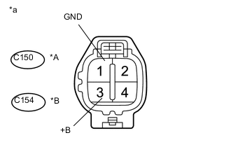
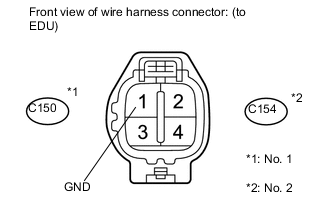
Text in Illustration *A for Bank 1 (No. 1 injector Driver (EDU)) *B for Bank 2 (No. 2 injector Driver (EDU)) *a Front view of wire harness connector
(to Injector Driver (EDU))
Disconnect the No. 1 or No. 2 injector driver (EDU) connector.
-
Turn the engine switch on (IG).
-
Measure the voltage according to the value(s) in the table below.
Standard Voltage Tester Connection Switch Condition Specified Condition C150-3 (+B) - C150-1 (GND) Engine switch on (IG) 11 to 14 V C154-3 (+B) - C154-1 (GND) Engine switch on (IG) 11 to 14 V -
Reconnect the No. 1 or No. 2 injector driver (EDU) connector.
OK 
CHECK FOR INTERMITTENT PROBLEMS Click here
NG 
-
-
INSPECT FUSE (EFI MAIN AND EFI MAIN 2)
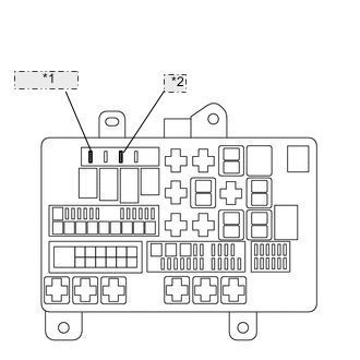
Engine Room Relay Block *1 EFI MAIN 2 *2 EFI MAIN
-
Remove the EFI MAIN and EFI MAIN 2 fuse from the engine room relay block.
-
Measure the resistance according to the value(s) in the table below.
Standard Resistance Tester Connection Condition Specified Condition EFI MAIN fuse Always Below 1 Ω EFI MAIN 2 fuse Always Below 1 Ω
NG
CHECK FOR SHORTS IN ALL HARNESSES AND CONNECTORS CONNECTED TO FUSE AND REPLACE FUSE
OK
-
-
INSPECT EDU RELAY (EDU 1 OR EDU 2)
-
Inspect the EDU relay (EDU 1 or EDU 2) Click here.
NG
REPLACE EDU RELAY (EDU 1 OR EDU 2)
OK
-
-
INSPECT INTEGRATION RELAY (EFI OR EFI MAIN 2)
-
Inspect the integration relay (EFI or EFI MAIN 2) Click here.
NG
REPLACE INTEGRATION RELAY
OK
-
-
CHECK HARNESS AND CONNECTOR (EDU RELAY - EDU)
-
Remove the EDU relay (EDU 1 or EDU 2) from the engine room relay block.
-
Remove the EDU connector.
-
Measure the resistance according to the value(s) in the table below.
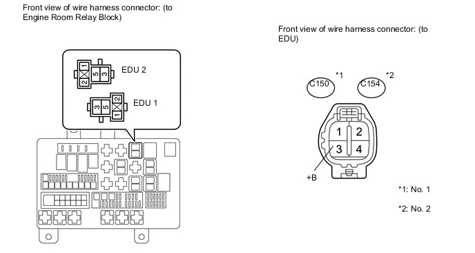
Standard Resistance No. 1 Tester Connection Condition Specified Condition EDU 1 relay (5) - C150-3 (+B) Always Below 1 Ω EDU 1 relay (5) or C150-3 (+B) - Body ground Always 10 kΩ or higher No. 2 Tester Connection Condition Specified Condition EDU 2 relay (5) - C154-3 (+B) Always Below 1 Ω EDU 2 relay (5) or C154-3 (+B) - Body ground Always 10 kΩ or higher
NG
REPAIR OR REPLACE HARNESS OR CONNECTOR
OK
-
-
CHECK HARNESS AND CONNECTOR (EDU RELAY - ECM)
-
Remove the EDU relay (EDU 1 or EDU 2) from the engine room relay block.
-
Disconnect the ECM connector.
-
Measure the resistance according to the value(s) in the table below.
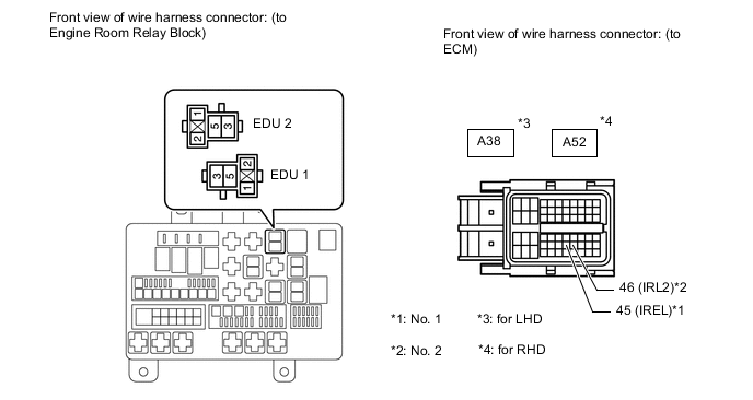
Standard Resistance No. 1 (LHD) Tester Connection Condition Specified Condition EDU 1 relay (2) - A38-45 (IREL) Always Below 1 Ω EDU 1 relay (2) or A38-45 (IREL) - Body ground Always 10 kΩ or higher No. 2 (LHD) Tester Connection Condition Specified Condition EDU 2 relay (2) - A38-46 (IRL2) Always Below 1 Ω EDU 2 relay (2) or A38-46 (IRL2) - Body ground Always 10 kΩ or higher No. 1 (RHD) Tester Connection Condition Specified Condition EDU 1 relay (2) - A52-45 (IREL) Always Below 1 Ω EDU 1 relay (2) or A52-45 (IREL) - Body ground Always 10 kΩ or higher No. 2 (RHD) Tester Connection Condition Specified Condition EDU 2 relay (2) - A52-46 (IRL2) Always Below 1 Ω EDU 2 relay (2) or A52-46 (IRL2) - Body ground Always 10 kΩ or higher
NG
REPAIR OR REPLACE HARNESS OR CONNECTOR
OK
-
-
CHECK HARNESS AND CONNECTOR (INTEGRATION RELAY - EDU RELAY, ECM, BODY GROUND)
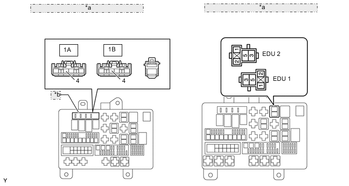
*a Front view of wire harness connector: (to Engine Room Relay Block) *b Integration Relay
-
Remove the integration relay from the engine room relay block.
-
Remove the EDU relay (EDU 1 or EDU 2).
-
Measure the resistance according to the value(s) in the table below.
Standard Resistance No. 1 Tester Connection Condition Specified Condition 1B-4 - EDU 1 relay (1) Always Below 1 Ω 1B-4 - EDU 1 relay (3) Always Below 1 Ω 1B-4 or EDU 1 relay (1) - Body ground Always 10 kΩ or higher 1B-4 or EDU 1 relay (3) - Body ground Always 10 kΩ or higher No. 2 Tester Connection Condition Specified Condition 1A-4 - EDU 2 relay (1) Always Below 1 Ω 1A-4 - EDU 2 relay (3) Always Below 1 Ω 1A-4 or EDU 2 relay (1) - Body ground Always 10 kΩ or higher 1A-4 or EDU 2 relay (3) - Body ground Always 10 kΩ or higher 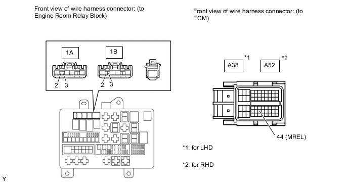
-
Disconnect the ECM connector.
-
Measure the resistance according to the value(s) in the table below.
Standard Resistance (Check for Open) No. 1 (LHD) Tester Connection Condition Specified Condition 1B-2 - A38-44 (MREL) Always Below 1 Ω 1B-3 - Body ground Always Below 1 Ω 1B-2 or A38-44 (MREL) - Body ground Always 10 kΩ or higher No. 2 (LHD) Tester Connection Condition Specified Condition 1A-2 - A38-44 (MREL) Always Below 1 Ω 1A-3 - Body ground Always Below 1 Ω 1A-2 or A38-44 (MREL) - Body ground Always 10 kΩ or higher No. 1 (RHD) Tester Connection Condition Specified Condition 1B-2 - A52-44 (MREL) Always Below 1 Ω 1B-3 - Body ground Always Below 1 Ω 1B-2 or A52-44 (MREL) - Body ground Always 10 kΩ or higher No. 2 (RHD) Tester Connection Condition Specified Condition 1A-2 - A52-44 (MREL) Always Below 1 Ω 1A-3 - Body ground Always Below 1 Ω 1A-2 or A52-44 (MREL) - Body ground Always 10 kΩ or higher
NG
REPAIR OR REPLACE HARNESS OR CONNECTOR
OK
-
-
CHECK HARNESS AND CONNECTOR (EDU - BODY GROUND)
-
Disconnect the EDU connector.
-
Measure the resistance according to the value(s) in the table below.
Standard Resistance No. 1 Tester Connection Condition Specified Condition C150-1 (GND) - Body ground Always Below 1 Ω Standard Resistance No. 2 Tester Connection Condition Specified Condition C154-1 (GND) - Body ground Always Below 1 Ω
OK
CHECK ECM POWER SOURCE CIRCUIT Click here
NG
REPAIR OR REPLACE HARNESS OR CONNECTOR (EDU - BODY GROUND)
-