ECD SYSTEM(w/ DPF) TERMINALS OF ECM
Measure the voltage according to the value(s) in the table below.
Tech Tips
The standard normal voltage between each pair of ECM terminals is shown in the table below. The appropriate conditions for checking each pair of terminals are also indicated.
The result of the checks should be compared with the standard normal voltage for that pair of terminals, which is displayed in the Specified Condition column.
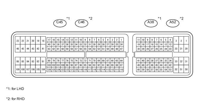
The illustration above can be used as a reference to identify the ECM terminal locations.
| Terminal No. (Symbol) | Wiring Color | Terminal Description | Condition | Specified Condition |
|---|---|---|---|---|
| A38*1-20 (BATT) - C45*1-81 (E1) A52*2-20 (BATT) - C46*2-81 (E1) |
L - BR | Battery (for measuring the battery voltage and for the ECM memory) | Always | 11 to 14 V |
| A38*1-28 (IGSW) - C45*1-81 (E1) A52*2-28 (IGSW) - C46*2-81 (E1) |
B - BR | Ignition switch | Ignition switch ON | 11 to 14 V |
| A38*1-2 (+B) - C45*1-81 (E1) A52*2-2 (+B) - C46*2-81 (E1) |
B - BR | Power source of ECM | Ignition switch ON | 11 to 14 V |
| A38*1-1 (+B2) - C45*1-81 (E1) A52*2-1 (+B2) - C46*2-81 (E1) |
B - BR | Power source of ECM | Ignition switch ON | 11 to 14 V |
| A38*1-44 (MREL) - C45*1-81 (E1) A52*2-44 (MREL) - C46*2-81 (E1) |
V - BR | EFI relay | Ignition switch ON | 11 to 14 V |
| 10 seconds elapsed after ignition switch turned off | 0 to 1.5 V | |||
| C45*1-66 (VCPM) - C45*1-92 (E2) C46*2-66 (VCPM) - C46*2-92 (E2) |
L - BR | Power source of manifold absolute pressure sensor (for PIM) | Ignition switch ON | 4.5 to 5.5 V |
| C45*1-118 (VCM) - C45*1-95 (E2M) C46*2-118 (VCM) - C46*2-95 (E2M) |
L - BR | Power source of fuel pressure sensor (for PCR1) | Ignition switch ON | 4.5 to 5.5 V |
| C45*1-91 (VC) - C45*1-92 (E2) C46*2-91 (VC) - C46*2-92 (E2) |
B - BR | Power source of EGR valve position sensor and differential pressure sensor | Ignition switch ON | 4.5 to 5.5 V |
| C45*1-110 (VCVL) - C45*1-87 (EVLU) C46*2-110 (VCVL) - C46*2-87 (EVLU) |
L - BR | Power source of throttle position sensor | Ignition switch ON | 4.5 to 5.5 V |
| C45*1-71 (VG) - C45*1-94 (EVG) C46*2-71 (VG) - C46*2-94 (EVG) |
L-Y - G-W | Mass air flow meter | Idling | Pulse generation |
| C45*1-115 (THA) - C45*1-92 (E2) C46*2-115 (THA) - C46*2-92 (E2) |
P - BR | Intake air temperature sensor (built into mass air flow meter) | Engine warmed up and idling, intake air temperature at 0 to 80°C (32 to 176°F) | 0.5 to 3.4 V |
| A38*1-53 (VPA) - A38*1-57 (EPA) A52*2-53 (VPA) - A52*2-57 (EPA) |
R - W | Accelerator pedal position sensor (for engine control) | Ignition switch ON, accelerator pedal fully released | 0.6 to 1.0 V |
| Ignition switch ON, accelerator pedal fully depressed | 3.0 to 4.6 V | |||
| A38*1-54 (VPA2) - A38*1-58 (EPA2) A52*2-54 (VPA2) - A52*2-58 (EPA2) |
GR - BE | Accelerator pedal position sensor (for sensor malfunction detection) | Ignition switch ON, accelerator pedal fully released | 1.4 to 1.8 V |
| Ignition switch ON, accelerator pedal fully depressed | 3.7 to 5.0 V | |||
| A38*1-55 (VCPA) - A38*1-57 (EPA) A52*2-55 (VCPA) - A52*2-57 (EPA) |
L - W | Power source of accelerator pedal position sensor (for VPA) | Ignition switch ON | 4.5 to 5.5 V |
| A38*1-56 (VCP2) - A38*1-58 (EPA2) A52*2-56 (VCP2) - A52*2-58 (EPA2) |
V - BE | Power source of accelerator pedal position sensor (for VPA2) | Ignition switch ON | 4.5 to 5.5 V |
| C45*1-90 (THIA) - C45*1-92 (E2) C46*2-90 (THIA) - C46*2-92 (E2) |
W - BR | Intake air temperature sensor (turbo) | Engine warmed up and idling, intake air temperature sensor (after turbocharged) at 0 to 80°C (32 to 176°F) | 0.5 to 3.4 V |
| C45*1-93 (THW) - C45*1-92 (E2) C46*2-93 (THW) - C46*2-92 (E2) |
LG - BR | Engine coolant temperature sensor | Engine warmed up and idling, engine coolant temperature at 60 to 120°C (140 to 248°F) | 0.2 to 1.2 V |
| C45*1-40 (#1) - C45*1-81 (E1) C46*2-40 (#1) - C46*2-81 (E1) |
L - BR | Injector assembly | Idling | Pulse generation (see waveform 1) |
| C45*1-39 (#2) - C45*1-81 (E1) C46*2-39 (#2) - C46*2-81 (E1) |
B - BR | |||
| C45*1-38 (#3) - C45*1-81 (E1) C46*2-38 (#3) - C46*2-81 (E1) |
L - BR | |||
| C45*1-37 (#4) - C45*1-81 (E1) C46*2-37 (#4) - C46*2-81 (E1) |
R - BR | |||
| C45*1-36 (#5) - C45*1-81 (E1) C46*2-36 (#5) - C46*2-81 (E1) |
G - BR | |||
| C45*1-35 (#6) - C45*1-81 (E1) C46*2-35 (#6) - C46*2-81 (E1) |
V - BR | |||
| C45*1-34 (#7) - C45*1-81 (E1) C46*2-34 (#7) - C46*2-81 (E1) |
W - BR | |||
| C45*1-33 (#8) - C45*1-81 (E1) C46*2-33 (#8) - C46*2-81 (E1) |
P - BR | |||
| C45*1-80 (G+) - C45*1-79 (G-) C46*2-80 (G+) - C46*2-79 (G-) |
W - B | Camshaft position sensor | Idling | Pulse generation |
| C45*1-78 (NE+) - C45*1-77 (NE-) C46*2-78 (NE+) - C46*2-77 (NE-) |
B - W | Crankshaft position sensor | Idling | Pulse generation |
| C45*1-67 (PIM) - C45*1-92 (E2) C46*2-67 (PIM) - C46*2-92 (E2) |
P - BR | Manifold absolute pressure sensor | Negative pressure of 40 kPa (300 mmHg, 11.8 in.Hg) applied | 0.1 to 0.7 V |
| Same as atmospheric pressure | 0.8 to 1.4 V | |||
| Positive pressure of 170 kPa (1275 mmHg, 50.2 in.Hg) applied | 1.6 to 2.2 V | |||
| A38*1-45 (IREL) - C45*1-81 (E1) A52*2-45 (IREL) - C46*2-81 (E1) |
LG - BR | EDU relay (EDU 1) | Ignition switch off | 11 to 14 V |
| Idling | 0 to 1.5 V | |||
| A38*1-46 (IRL2) - C45*1-81 (E1) A52*2-46 (IRL2) - C46*2-81 (E1) |
V - BR | EDU relay (EDU 2) | Ignition switch off | 11 to 14 V |
| Idling | 0 to 1.5 V | |||
| C45*1-72 (PCR1) - C45*1-95 (E2M) C46*2-72 (PCR1) - C46*2-95 (E2M) |
B - BR | Fuel pressure sensor | Idling (Approximately 35 MPa (357 kgf/cm2, 5078 psi)) |
1.3 to 1.8 V |
| A38*1-12 (GREL) - C45*1-81 (E1) A52*2-12 (GREL) - C46*2-81 (E1) |
V - BR | No. 1 glow relay | Cranking | 11 to 14 V |
| Idling | 0 to 1.5 V | |||
| A38*1-23 (GRL2) - C45*1-81 (E1) A52*2-23 (GRL2) - C46*2-81 (E1) |
LG - BR | No. 2 glow relay | Cranking | 11 to 14 V |
| Idling | 0 to 1.5 V | |||
| C45*1-116 (THF) - C45*1-92 (E2) C46*2-116 (THF) - C46*2-92 (E2) |
G - BR | Fuel temperature sensor | Ignition switch ON | 0.5 to 3.4 V |
| C45*1-104 (PCV+) - C45*1-105 (PCV-) C46*2-104 (PCV+) - C46*2-105 (PCV-) |
W - BR | Suction control valve | Idling | Pulse generation (see waveform 2) |
| C45*1-60 (INJ1) - C45*1-81 (E1) C46*2-60 (INJ1) - C46*2-81 (E1) |
G - BR | No. 1 injector driver | Idling | Pulse generation (see waveform 3) |
| C45*1-61 (INJ2) - C45*1-81 (E1) C46*2-61 (INJ2) - C46*2-81 (E1) |
W - BR | No. 2 injector driver | Idling | Pulse generation (see waveform 3) |
| C45*1-64 (VLU) - C45*1-87 (EVLU) C46*2-64 (VLU) - C46*2-87 (EVLU) |
P - BR | Throttle position sensor (for Bank 1) | Ignition switch ON (throttle valve fully opened) |
2.8 to 3.8 V |
| Idling (throttle valve fully closed) |
0.4 to 1.0 V | |||
| C45*1-65 (VLU2) - C45*1-87 (EVLU) C46*2-65 (VLU2) - C46*2-87 (EVLU) |
L - BR | Throttle position sensor (for Bank 2) | Ignition switch ON (throttle valve fully opened) |
2.8 to 3.8 V |
| Idling (throttle valve fully closed) |
0.4 to 1.0 V | |||
| C45*1-57 (LUSL) - C45*1-81 (E1) C46*2-57 (LUSL) - C46*2-81 (E1) |
GR - BR | Diesel throttle duty signal (for Bank 1) | Engine warmed up, racing engine | Pulse generation (see waveform 4) |
| C45*1-56 (LUS2) - C45*1-81 (E1) C46*2-56 (LUS2) - C46*2-81 (E1) |
BE - BR | Diesel throttle duty signal (for Bank 2) | Engine warmed up, racing engine | Pulse generation (see waveform 4) |
| C45*1-88 (EGLS) - C45*1-92 (E2) C46*2-88 (EGLS) - C46*2-92 (E2) |
R - BR | No. 1 EGR valve position sensor | Ignition switch ON | 3.0 to 4.6 V |
| C45*1-89 (EGS2) - C45*1-92 (E2) C46*2-89 (EGS2) - C46*2-92 (E2) |
SB - BR | No. 2 EGR valve position sensor | Ignition switch ON | 3.0 to 4.6 V |
| C45*1-82 (EGRS) - C45*1-81 (E1) C46*2-82 (EGRS) - C46*2-81 (E1) |
V - BR | No. 1 EGR valve assembly | Engine warmed up and idling | Pulse generation (see waveform 5) |
| C45*1-42 (ERS2) - C45*1-81 (E1) C46*2-42 (ERS2) - C46*2-81 (E1) |
R - BR | No. 2 EGR valve assembly | Engine warmed up and idling | Pulse generation (see waveform 5) |
| C45*1-86 (M+) - C45*1-81 (E1) C46*2-86 (M+) - C46*2-81 (E1) |
G - BR | DC motor (turbocharger sub-assembly for Bank 1) | Idling | Pulse generation (see waveform 6) |
| C45*1-18 (VN2+) - C45*1-81 (E1) C46*2-18 (VN2+) - C46*2-81 (E1) |
W - BR | DC motor (turbocharger sub-assembly for Bank 2) | Idling | Pulse generation (see waveform 6) |
| C45*1-85 (M-) - C45*1-81 (E1) C46*2-85 (M-) - C46*2-81 (E1) |
B - BR | DC motor (turbocharger sub-assembly for Bank 1) | Idling | Pulse generation (see waveform 7) |
| C45*1-41 (VN2-) - C45*1-81 (E1) C46*2-41 (VN2-) - C46*2-81 (E1) |
B - BR | DC motor (turbocharger sub-assembly for Bank 2) | Idling | Pulse generation (see waveform 7) |
| A38*1-13 (STP) - C45*1-81 (E1) A52*2-13 (STP) - C46*2-81 (E1) |
R - BR | Stop light switch | Ignition switch ON, brake pedal depressed | 7.5 to 14 V |
| Ignition switch ON, brake pedal released | 0 to 1.5 V | |||
| A38*1-35 (ST1-) - C45*1-81 (E1) A52*2-35 (ST1-) - C46*2-81 (E1) |
P - BR | Stop light switch (opposite to STP) |
Ignition switch ON, brake pedal depressed | 0 to 1.5 V |
| Ignition switch ON, brake pedal released | 7.5 to 14 V | |||
| A38*1-15 (TACH) - C45*1-81 (E1) A52*2-15 (TACH) - C46*2-81 (E1) |
W - BR | Engine speed | Idling | Pulse generation (see waveform 8) |
| A38*1-8 (SPD) - C45*1-81 (E1) A52*2-8 (SPD) - C46*2-81 (E1) |
V - BR | Speed signal from combination meter | Ignition switch ON, wheel rotated slowly | Pulse generation (see waveform 9) |
| A38*1-48 (STA) - C45*1-81 (E1) A52*2-48 (STA) - C46*2-81 (E1) |
R - BR | Starter signal | Cranking | 6.0 V or more |
| C45*1-53 (ALT) - C45*1-81 (E1) C46*2-53 (ALT) - C46*2-81 (E1) |
R - BR | Generator duty ratio | Idling | Pulse generation |
| A38*1-27 (TC) - C45*1-81 (E1) A52*2-27 (TC) - C46*2-81 (E1) |
V - BR | Terminal TC of DLC3 | Ignition switch ON | 11 to 14 V |
| A38*1-30 (AC1) - C45*1-81 (E1) A52*2-30 (AC1) - C46*2-81 (E1) |
L - BR | A/C signal | A/C switch on | 0 to 1.5 V |
| A/C switch off | 11 to 14 V | |||
| A38*1-18 (ACT) - C45*1-81 (E1) A52*2-18 (ACT) - C46*2-81 (E1) |
G - BR | A/C signal | Ignition switch ON | 11 to 14 V |
| A/C cut control on | 0 to 3 V | |||
| C45*1-55 (PSW) - C45*1-81 (E1) C46*2-55 (PSW) - C46*2-81 (E1) |
P - BR | Power steering oil pressure switch | Steering wheel turned | 0 to 3 V |
| Steering wheel not turned | 11 to 14 V | |||
| A38*1-52 (ACM) - C45*1-81 (E1) A52*2-52 (ACM) - C46*2-81 (E1) |
L - BR | VSV (for engine mounting) | Idling | 0 to 1.5 V |
| C45*1-49 (NSW) - C45*1-81 (E1) C46*2-49 (NSW) - C46*2-81 (E1) |
L - BR | Park/neutral position switch | Ignition switch ON, shift lever in P or N | Below 3 V |
| Ignition switch ON, shift lever not in P and N | 11 to 14 V | |||
| A38*1-41 (CANH) - C45*1-81 (E1) A52*2-41 (CANH) - C46*2-81 (E1) |
P - BR | CAN communication line | Ignition switch ON | Pulse generation (see waveform 10) |
| A38*1-49 (CANL) - C45*1-81 (E1) A52*2-49 (CANL) - C46*2-81 (E1) |
B - BR | CAN communication line | Ignition switch ON | Pulse generation (see waveform 11) |
| C45*1-54 (PRD) - C45*1-81 (E1) C46*2-54 (PRD) - C46*2-81 (E1) |
L - BR | Pressure discharge valve drive signal | Engine warmed up, engine racing | Pulse generation (See waveform 12) |
| C45*1-32 (RLFF) - C45*1-81 (E1) C46*2-32 (RLFF) - C46*2-81 (E1) |
R - BR | Pressure discharge valve confirmation signal | Engine warmed up, engine racing | Pulse generation (See waveform 12) |
| C45*1-120 (VNVC) - C45*1-97 (VNE2) C46*2-120 (VNVC) - C46*2-97 (VNE2) |
W - R | Power source of nozzle vane position sensor | Ignition switch ON | 4.5 to 5.5 V |
| C45*1-74 (VNA) - C45*1-97 (VNE2) C46*2-74 (VNA) - C46*2-97 (VNE2) |
BR - R | Nozzle vane position sensor (for bank 1) | Ignition switch ON | 2.3 to 2.7 V |
| C45*1-117 (VNA2) - C45*1-97 (VNE2) C46*2-117 (VNA2) - C46*2-97 (VNE2) |
B - R | Nozzle vane position sensor (for bank 2) | Ignition switch ON | 2.3 to 2.7 V |
| C45*1-122 (THCF) - C45*1-99 (ETCF) C46*2-122 (THCF) - C46*2-99 (ETCF) |
L - BR | Exhaust gas temperature sensor (B1S1) | Engine warmed up, idling | 4.6 to 4.9 V |
| C45*1-121 (THCI) - C45*1-99 (ETCF) C46*2-121 (THCI) - C46*2-99 (ETCF) |
B - BR | No. 2 Exhaust gas temperature sensor (B1S2) | Engine warmed up, idling | 4.6 to 4.9 V |
| C45*1-123 (THCO) - C45*1-99 (ETCF) C46*2-123 (THCO) - C46*2-99 (ETCF) |
W - BR | No. 4 Exhaust gas temperature sensor (B1S3) | Engine warmed up, idling | 4.6 to 4.9 V |
| C45*1-68 (TCF2) - C45*1-99 (ETCF) C46*2-68 (TCF2) - C46*2-99 (ETCF) |
G - BR | Exhaust gas temperature sensor (B2S1) | Engine warmed up, idling | 4.6 to 4.9 V |
| C45*1-98 (TCI2) - C45*1-99 (ETCF) C46*2-98 (TCI2) - C46*2-99 (ETCF) |
P - BR | No. 3 Exhaust gas temperature sensor (B2S2) | Engine warmed up, idling | 4.6 to 4.9 V |
| C45*1-124 (TCO2) - C45*1-99 (ETCF) C46*2-124 (TCO2) - C46*2-99 (ETCF) |
P - BR | No. 4 Exhaust gas temperature sensor (B2S3) | Engine warmed up, idling | 4.6 to 4.9 V |
| C45*1-83 (FIV) - C45*1-81 (E1) C46*2-83 (FIV) - C46*2-81 (E1) |
W - BR | Exhaust fuel addition injector assembly (for bank 1) | Exhaust fuel addition injector assembly (for bank 1) operating | Pulse generation |
| C45*1-84 (FIV2) - C45*1-81 (E1) C46*2-84 (FIV2) - C46*2-81 (E1) |
G - BR | Exhaust fuel addition injector assembly (for bank 2) | Exhaust fuel addition injector assembly (for bank 2) operating | Pulse generation |
| C45*1-45 (HA1A) - C45*1-44 (E04) C46*2-45 (HA1A) - C46*2-44 (E04) |
L - BR | Air fuel ratio sensor heater (for bank 1) | Ignition switch ON | Pulse generation |
| C45*1-102 (A1A+) - C45*1-44 (E04) C46*2-102 (A1A+) - C46*2-44 (E04) |
G - BR | Air fuel ratio sensor (for bank 1) | Ignition switch ON | 2.0 to 2.5 V |
| C45*1-103 (A1A-) - C45*1-44 (E04) C46*2-103 (A1A-) - C46*2-44 (E04) |
R - BR | Air fuel ratio sensor (for bank 1) | Ignition switch ON | 2.0 to 2.5 V |
| C45*1-46 (HA2A) - C45*1-23 (E05) C46*2-46 (HA2A) - C46*2-23 (E05) |
L - W-B | Air fuel ratio sensor heater (for bank 2) | Ignition switch ON | Pulse generation |
| C45*1-125 (A2A+) - C45*1-23 (E05) C46*2-125 (A2A+) - C46*2-23 (E05) |
G - W-B | Air fuel ratio sensor (for bank 2) | Ignition switch ON | 2.0 to 2.5 V |
| C45*1-126 (A2A-) - C45*1-23 (E05) C46*2-126 (A2A-) - C46*2-23 (E05) |
R - W-B | Air fuel ratio sensor (for bank 2) | Ignition switch ON | 2.0 to 2.5 V |
| C45*1-69 (PEX) - C45*1-92 (E2) C46*2-69 (PEX) - C46*2-92 (E2) |
R - BR | Differential pressure sensor (for bank 1) | Ignition switch ON | 0.4 to 4.8 V |
| C45*1-70 (PEX2) - C45*1-92 (E2) C46*2-70 (PEX2) - C46*2-92 (E2) |
R - BR | Differential pressure sensor (for bank 2) | Ignition switch ON | 0.4 to 4.8 V |
Tech Tips
-
*1: for LHD
-
*2: for RHD
-
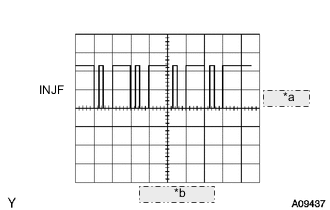
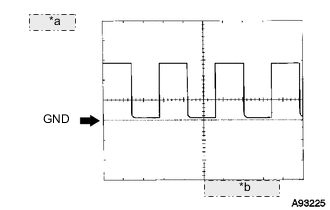
WAVEFORM 1
*a 5 V/DIV. *b 20 msec./DIV. Injector Assembly No. 1 (to No. 8) Injection Signal ECM Terminal Name #1 to #8 and E1 Tester Range 5 V/DIV., 20 msec./DIV. Condition Idling with warm engine Tech Tips
The waveform varies depending on the injector injection.
-
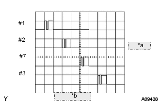
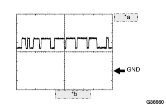
WAVEFORM 2
*a 10 V/DIV. *b 5 msec./DIV. Suction Control Valve Signal ECM Terminal Name PCV+ and PCV- Tester Range 10 V/DIV., 5 msec./DIV. Condition Idling or cranking with warm engine Tech Tips
The waveform varies depending on the suction control valve operation.
-
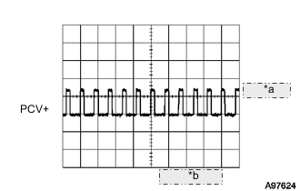
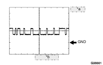
WAVEFORM 3
*a 2 V/DIV. *b 20 msec./DIV. Injector Injection Confirmation Signal ECM Terminal Name INJ1 and E1
INJ2 and E1
Tester Range 2 V/DIV., 20 msec./DIV. Condition Idling with warm engine Tech Tips
The waveform varies depending on the injector injection.
-
WAVEFORM 4
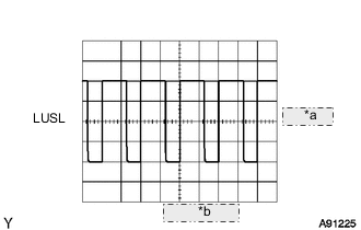
*a 1 V/DIV. *b 2 msec./DIV. Diesel Throttle Motor Signal ECM Terminal Name LUSL and E1
LUS2 and E1
Tester Range 1 V/DIV., 2 msec./DIV. Condition Racing with warm engine Tech Tips
The waveform varies depending on the throttle valve operation.
-
WAVEFORM 5
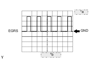
*a 5 V/DIV. *b 5 msec./DIV. EGR Position Sensor Signal ECM Terminal Name EGRS and E1
ERS2 and E1
Tester Range 5 V/DIV., 5 msec./DIV. Condition Idling Tech Tips
The waveform varies depending on the throttle valve operation.
-
WAVEFORM 6
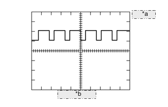
*a 5 V/DIV. *b 20 msec./DIV. DC Motor Positive Terminal Signal ECM Terminal Name M+ and E1
VN2+ and E1
Tester Range 5 V/DIV., 20 msec./DIV. Condition Idling with warm engine Tech Tips
The waveform varies depending on the turbocharger operation.
-
WAVEFORM 7
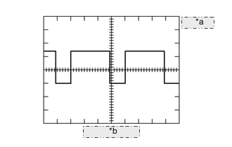
*a 5 V/DIV. *b 50 msec./ DIV. DC Motor Negative Terminal Signal ECM Terminal Name M- and E1
VN2- and E1
Tester Range 5 V/DIV., 50 msec./DIV. Condition Idling with warm engine Tech Tips
The waveform varies depending on the turbocharger status.
-
WAVEFORM 8
*a 5 V/DIV. *b 10 msec./DIV. Engine Speed Signal ECM Terminal Names TACH and E1 Tester Range 5 V/DIV., 10 msec./DIV. Conditions Idling Tech Tips
The wavelength becomes shorter as the engine speed increases.
-
WAVEFORM 9
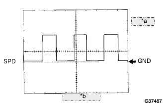
*a 5 V/DIV. *b 10 msec./DIV. Vehicle Speed Signal ECM Terminal Name SPD and E1 Tester Range 5 V/DIV., 10 msec./DIV. Condition Driving at vehicle speed of 40 km/h (25 mph) Tech Tips
The wavelength becomes shorter as the vehicle speed increases.
-
WAVEFORM 10
*a 1 V/DIV. *b 10 msec./DIV CAN Communication Signal ECM Terminal Name CAN+ and E1 Tester Range 1 V/DIV., 10 msec./DIV. Condition Engine stopped, ignition switch ON Tech Tips
The waveform varies depending on the CAN communication signal.
-
WAVEFORM 11
*a 1 V/DIV. *b 10 msec./DIV. CAN Communication Signal ECM Terminal Name CAN- and E1 Tester Range 1 V/DIV., 10 msec./DIV. Condition Engine stopped, ignition switch ON Tech Tips
The waveform varies depending on the CAN communication signal.
-
WAVEFORM 12
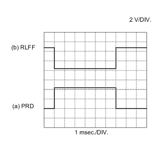
Pressure Discharge Valve Drive Signal and Pressure Discharge Confirmation Signal ECM Terminal Name (a) PRD and E1
(b) RLFF and E1
Tester Range 2 V/DIV., 1 msec./DIV. Condition Engine warmed up, engine racing Tech Tips
The wavelength becomes shorter as the engine speed increases.