SFI SYSTEM(w/o Secondary Air Injection System), Diagnostic DTC:P2237, P2238, P2239, P2240, P2241, P2242, P2252, P2253, P2255, P2256
| DTC Code | DTC Name |
|---|---|
| P2237 | Oxygen (A/F) Sensor Pumping Current Circuit / Open (Bank 1 Sensor 1) |
| P2238 | Oxygen (A/F) Sensor Pumping Current Circuit Low (Bank 1 Sensor 1) |
| P2239 | Oxygen (A/F) Sensor Pumping Current Circuit High (Bank 1 Sensor 1) |
| P2240 | Oxygen (A/F) Sensor Pumping Current Circuit / Open (Bank 2 Sensor 1) |
| P2241 | Oxygen (A/F) Sensor Pumping Current Circuit Low (Bank 2 Sensor 1) |
| P2242 | Oxygen (A/F) Sensor Pumping Current Circuit High (Bank 2 Sensor 1) |
| P2252 | Oxygen (A/F) Sensor Reference Ground Circuit Low (Bank 1 Sensor 1) |
| P2253 | Oxygen (A/F) Sensor Reference Ground Circuit High (Bank 1 Sensor 1) |
| P2255 | Oxygen (A/F) Sensor Reference Ground Circuit Low (Bank 2 Sensor 1) |
| P2256 | Oxygen (A/F) Sensor Reference Ground Circuit High (Bank 2 Sensor 1) |
DESCRIPTION
Refer to DTC P0031 Click here.
| DTC Code | DTC Detection Condition | Trouble Area |
|---|---|---|
| P2237 P2240 |
An open in the circuit between terminals A1A+ and A1A-/A2A+ and A2A- of the A/F sensor while the engine is running (2 trip detection logic). |
|
| P2238 P2241 |
Condition (a) or (b) continues for 5.0 seconds or more (1 trip detection logic): (a) The A1A+/A2A+ voltage is 0.5 V or less. (b) (A1A+/A2A+) - (A1A-/A2A-) = 0.1 V or less.
The A/F sensor admittance is below 0.022 1/Ω (2 trip detection logic). |
|
| P2239 P2242 |
The A1A+/A2A+ voltage is higher than 4.5 V for 5.0 seconds or more (2 trip detection logic). |
|
| P2252 P2255 |
The A1A-/A2A- voltage is 0.5 V or less for 5.0 seconds or more (2 trip detection logic). |
|
| P2253 P2256 |
The A1A-/A2A- voltage is higher than 4.5 V for 5.0 seconds or more (2 trip detection logic). |
|
Tech Tips
-
DTCs P2237, P2238, P2239, P2252 and P2253 indicate malfunctions related to the bank 1 A/F sensor circuit.
-
DTCs P2240, P2241, P2242, P2255 and P2256 indicate malfunctions related to the bank 2 A/F sensor circuit.
MONITOR DESCRIPTION
These DTCs are stored when there is an open or short in the A/F sensor circuit, or if A/F sensor output drops.
To detect these problems, the voltage of the A/F sensor is monitored when turning the engine switch on (IG), and the admittance (admittance is an electrical term that indicates the ease of flow of current) is checked while driving. If the voltage of the A/F sensor is between 0.6 V and 4.5 V, it is considered normal. If the voltage is outside of the specified range, or the admittance is less than the standard value, the ECM will determine that there is a malfunction in the A/F sensor. If the same malfunction is detected in the next driving cycle, the MIL is illuminated and a DTC is stored.
The Air Fuel ratio (A/F) sensor varies its output voltage in proportion to the air-fuel ratio. If the A/F sensor impedance (alternating current resistance) or output voltage deviates greatly from the standard range, the ECM determines that there is an open or short in the A/F sensor circuit.
WIRING DIAGRAM
Refer to DTC P0031 Click here.
CAUTION / NOTICE / HINT
Tech Tips
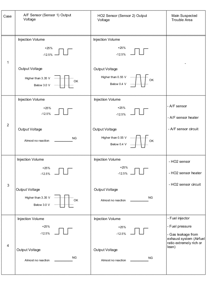
Malfunctioning areas can be identified by performing the Control the Injection Volume for A/F sensor function provided in the Active Test. The Control the Injection Volume for A/F sensor function can help to determine whether the Air Fuel ratio (A/F) sensor, Heated Oxygen (HO2) sensor and other potential trouble areas are malfunctioning.
The following instructions describe how to conduct the Control the Injection Volume for A/F sensor operation using the intelligent tester.
-
(a) Connect the tester to the DLC3.
-
(b) Start the engine and turn the tester on.
-
(c) Warm up the engine at an engine speed of 2500 rpm for approximately 90 seconds.
-
(d) Enter the following menus: Powertrain / Engine and ECT / Active Test / Control the Injection Volume for A/F sensor.
-
(e) Perform the Active Test operation with the engine idling (press the RIGHT or LEFT button to change the fuel injection volume).
-
(f) Monitor the output voltages of the A/F and HO2 sensors (AFS Voltage B1S1 and O2S B1S2 or AFS Voltage B2S1 and O2S B2S2) displayed on the tester.
Tech Tips
-
The Control the Injection Volume for A/F sensor operation lowers the fuel injection volume by 12.5% or increases the injection volume by 25%.
-
Each sensor reacts in accordance with increases and decreases in the fuel injection volume.
| Standard | ||||||||||||||||||||||||||||||||
|---|---|---|---|---|---|---|---|---|---|---|---|---|---|---|---|---|---|---|---|---|---|---|---|---|---|---|---|---|---|---|---|---|
|
Note
The A/F sensor has an output delay of a few seconds and the HO2 sensor has a maximum output delay of approximately 20 seconds.
-
Following the Control the Injection Volume for A/F Sensor procedure enables technicians to check and graph the output voltages of both the A/F and HO2 sensors.
-
To display the graph, enter the following menus: Powertrain / Engine and ECT / Active Test / Control the Injection Volume for A/F Sensor / A/F Control System / AFS Voltage B1S1 and O2S B1S2 or AFS Voltage B2S1 and O2S B2S2.
Tech Tips
-
Read freeze frame data using the intelligent tester. Freeze frame data records the engine condition when malfunctions are detected. When troubleshooting, freeze frame data can help determine if the vehicle was moving or stationary, if the engine was warmed up or not, if the air-fuel ratio was lean or rich, and other data from the time the malfunction occurred.
-
Bank 1 refers to the bank that includes the No. 1 cylinder*.
*: The No. 1 cylinder is the cylinder which is farthest from the transmission.
-
Bank 2 refers to the bank that does not include the No. 1 cylinder.
-
Sensor 1 refers to the sensor closest to the engine assembly.
-
Sensor 2 refers to the sensor farthest away from the engine assembly.
PROCEDURE
-
CHECK HARNESS AND CONNECTOR (A/F SENSOR - ECM)
-
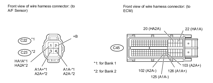
Disconnect the C22 or C23 Air Fuel ratio (A/F) sensor connector.
-
Measure the voltage according to the value(s) in the table below.
Standard Voltage Tester Connection Switch Condition Specified Condition C22-2 (+B) - Body ground Engine switch on (IG) 11 to 14 V C23-2 (+B) - Body ground Engine switch on (IG) 11 to 14 V -
Turn the engine switch off.
-
Disconnect the C45 ECM connector.
-
Measure the resistance according to the value(s) in the table below.
Standard Resistance Tester Connection Condition Specified Condition C22-1 (HA1A) - C45-22 (HA1A) Always Below 1 Ω C22-3 (A1A+) - C45-126 (A1A+) Always Below 1 Ω C22-4 (A1A-) - C45-125 (A1A-) Always Below 1 Ω C23-1 (HA2A) - C45-20 (HA2A) Always Below 1 Ω C23-3 (A2A+) - C45-103 (A2A+) Always Below 1 Ω C23-4 (A2A-) - C45-102 (A2A-) Always Below 1 Ω C22-1 (HA1A) or C45-22 (HA1A) - Body ground Always 10 kΩ or higher C22-3 (A1A+) or C45- 126 (A1A+) - Body ground Always 10 kΩ or higher C22-4 (A1A-) or C45-125 (A1A-) - Body ground Always 10 kΩ or higher C23-1 (HA2A) or C45-20 (HA2A) - Body ground Always 10 kΩ or higher C23-3 (A2A+) or C45- 103 (A2A+) - Body ground Always 10 kΩ or higher C23-4 (A2A-) or C45-102 (A2A-) - Body ground Always 10 kΩ or higher 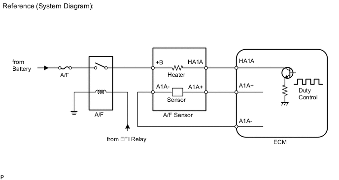
NG 
REPAIR OR REPLACE HARNESS OR CONNECTOR
OK 
-
-
REPLACE AIR FUEL RATIO SENSOR
-
Replace the air fuel ratio sensor Click here.
NEXT
-
-
CHECK WHETHER DTC OUTPUT RECURS
-
Connect the intelligent tester to the DLC3.
-
Turn the engine switch on (IG) and turn the tester on.
-
Clear DTCs Click here.
-
Start the engine.
-
Allow the engine to idle for 5 minutes or more.
-
Enter the following menus: Powertrain / Engine and ECT / DTC / Pending.
-
Read pending DTCs.
Result Result Proceed to No DTC is output A P2237, P2238, P2239, P2240, P2241, P2242, P2252, P2253, P2255 or P2256 is output B
A
END
B
REPLACE ECM Click here
-