THROTTLE BODY INSTALLATION
PROCEDURE
-
INSTALL THROTTLE BODY WITH MOTOR ASSEMBLY
-
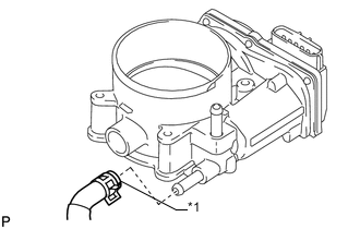
Text in Illustration *1 Paint Mark Install the No. 4 water by-pass hose to the throttle body with motor assembly.
Tech Tips
When installing the hose, make sure the paint mark and clip are as shown in the illustration.
-
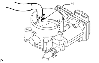
Text in Illustration *1 Paint Mark Install the No. 12 water by-pass hose to the throttle body with motor assembly.
Tech Tips
When installing the hose, make sure the paint mark and clip are as shown in the illustration.
-
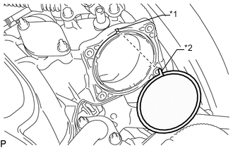
Text in Illustration *1 Groove *2 Protrusion Align the protrusion of a new gasket with the groove of the intake manifold and install the gasket to the intake manifold.
-
Install the throttle body with motor assembly with the 4 bolts.
- Torque:
- 10 N*m { 102 kgf*cm, 7 ft.*lbf }
-
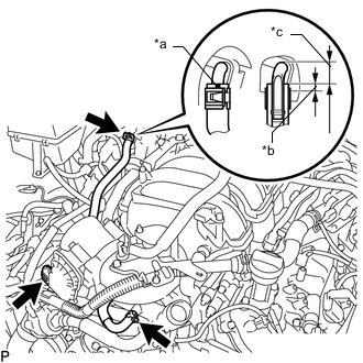
Text in Illustration *a Paint Mark *b 5 mm (0.197 in.) *c 13 to 17 mm (0.511 to 0.669 in.) Connect the throttle position sensor and control motor connector.
-
Connect the No. 4 water by-pass hose and No. 12 water by-pass hose.
Tech Tips
When connecting the No. 12 water by-pass hose, make sure the paint marks and clips are as shown in the illustration.
-
-
INSTALL AIR CLEANER CAP AND HOSE
-
Install the air cleaner cap and hose, and then tighten the hose clamp.
- Torque:
- 2.5 N*m { 25 kgf*cm, 22 in.*lbf }
-
Attach the 4 clamps.
-
Connect the mass air flow meter connector and attach the clamp.
-
Connect the No. 2 PCV hose and No. 1 air hose.
-
-
ADD ENGINE COOLANT
-
INSPECT FOR COOLANT LEAK
-
INSTALL NO. 1 ENGINE UNDER COVER SUB-ASSEMBLY
-
INSTALL FRONT FENDER SPLASH SHIELD SUB-ASSEMBLY RH
-
INSTALL FRONT FENDER SPLASH SHIELD SUB-ASSEMBLY LH
-
INSTALL V-BANK COVER SUB-ASSEMBLY
-
PERFORM INITIALIZATION
Note
-
Be sure to perform this procedure after reassembling the throttle body with motor assembly or removing and reinstalling any throttle body component.
-
Perform the following procedure after replacing the ECM, throttle body with motor assembly or any throttle body components. The following procedure should also be performed if the throttle body is cleaned.
-
Be sure to perform this procedure after reconnecting the battery cable and replacing the ECM.
-
Disconnect the EFI fuse, wait at least 60 seconds, and then reconnect the fuse.
-
Turn the engine switch on (IG) without operating the accelerator pedal.
Note
If the accelerator pedal is operated, perform the above steps again.
-
Connect the GTS to the DLC3 and clear the DTCs Click here.
-
Start the engine and check that the MIL is not illuminated and that the idle speed is within the specified range when the A/C is switched off after the engine is warmed up.
Standard Condition Engine Idle Speed A/C switched off 650 to 750 rpm Note
-
Be sure to perform this step with all accessories off.
-
Make sure that the shift lever is in N or P.
-
-
Enter the following menus: Powertrain / Engine and ETC / Data List / Throttle Sensor Volt %. Fully depress the accelerator pedal and check that the value is 60% or more.
-
Perform a road test and confirm that there are no abnormalities.
-