SFI SYSTEM, Diagnostic DTC:P1340, P1342, P1343
| DTC Code | DTC Name |
|---|---|
| P1340 | Camshaft Position Sensor "A" (Bank 1 Sensor 2) |
| P1342 | Camshaft Position Sensor "A" Low Input (MRE) |
| P1343 | Camshaft Position Sensor "A" High Input (MRE) |
DESCRIPTION
The camshaft position sensor (G signal) consists of a magnet and MRE (Magnetoresistive Element).
The camshaft timing gear (LH) has 3 teeth on its outer circumference. When the camshaft timing gear rotates, the air gap between the protrusion on the gear and the MRE changes. The change affects the magnetic field and results in changes in the resistance of the MRE.
The crankshaft angle sensor rotor has 34 teeth and is mounted on the crankshaft. The crankshaft position sensor generates 34 signals per crankshaft revolution. The ECM uses the G2 signal to distinguish between the cylinders, and uses the NE signal to detect the crankshaft position and engine speed.
| DTC No. | DTC Detection Condition | Trouble Area |
|---|---|---|
| P1340 | No camshaft position sensor signal is sent to the ECM during cranking (2 trip detection logic). |
|
| No camshaft position sensor signal is sent to the ECM with the engine speed at 600 rpm or more, or the camshaft position and crankshaft position phases are misaligned (1 trip detection logic). | ||
| P1342 | Output voltage of the camshaft position sensor is below 0.3 V for 4 seconds (1 trip detection logic). | |
| P1343 | Output voltage of the camshaft position sensor is higher than 4.7 V for 4 seconds (1 trip detection logic). |
-
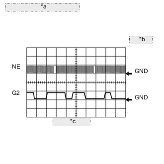
*a NE and G2 Signal Waveforms *b 5 V/DIV. *c 20 msec./DIV. Reference: Inspection using an oscilloscope.
Standard for RHD Tester Connection Tool Setting Condition Specified Condition C46-110 (NE+) - C46-111 (NE-) 5 V/DIV., 20 msec./DIV. Cranking or idling The correct waveform is as shown C46-90 (G2) - C46-89 (G2-) 5 V/DIV., 20 msec./DIV. Cranking or idling The correct waveform is as shown for LHD Tester Connection Tool Setting Condition Specified Condition C45-110 (NE+) - C45-111 (NE-) 5 V/DIV., 20 msec./DIV. Cranking or idling The correct waveform is as shown C45-90 (G2) - C45-89 (G2-) 5 V/DIV., 20 msec./DIV. Cranking or idling The correct waveform is as shown Tech Tips
G2 is the camshaft position sensor signal, and NE is the crankshaft position sensor signal.
MONITOR DESCRIPTION
If no signal is transmitted by the camshaft position sensor despite the engine running, or the rotations of the camshaft and crankshaft are not synchronized, the ECM interprets this as a malfunction of the sensor.
Also, when the sensor output voltage remains below 0.3 V, or higher than 4.7 V for more than 4 seconds, the ECM stores a DTC.
CONFIRMATION DRIVING PATTERN
-
Start the engine and run it at idle for 10 seconds or more.
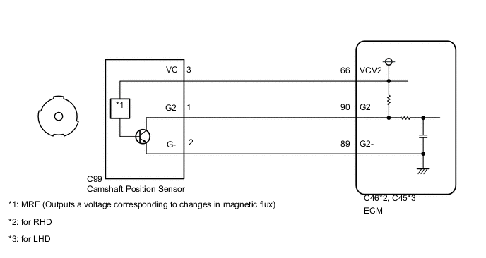
WIRING DIAGRAM
CAUTION / NOTICE / HINT
Tech Tips
Read freeze frame data using the GTS. Freeze frame data records the engine conditions when malfunctions are detected. When troubleshooting, freeze frame data can help determine if the vehicle was moving or stationary, if the engine was warmed up or not, if the air fuel ratio was lean or rich, and other data from the time the malfunction occurred.
PROCEDURE
-
INSPECT CAMSHAFT POSITION SENSOR (SENSOR POWER SOURCE)
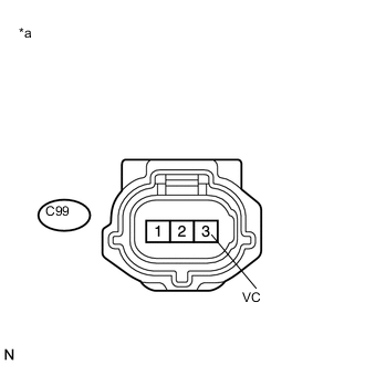
Text in Illustration *a Front view of wire harness connector
(to Camshaft Position Sensor)
-
Disconnect the camshaft position sensor connector.
-
Turn the engine switch on (IG).
-
Measure the voltage according to the value(s) in the table below.
Standard Voltage Tester Connection Switch Condition Specified Condition C99-3 (VC) - Body ground Engine switch on (IG) 4.5 to 5.0 V
NG 
REPAIR OR REPLACE HARNESS OR CONNECTOR
OK 
-
-
CHECK HARNESS AND CONNECTOR (ECM - CAMSHAFT POSITION SENSOR)
-
Disconnect the camshaft position sensor connector.
-
Disconnect the ECM connector.
-
Measure the resistance according to the value(s) in the table below.
Standard Resistance for RHD Tester Connection Condition Specified Condition C99-1 (G2) - C46-90 (G2) Always Below 1 Ω C99-2 (G-) - C46-89 (G2-) Always Below 1 Ω C99-1 (G2) or C46-90 (G2) - Body ground Always 10 kΩ or higher C99-2 (G-) or C46-89 (G2-) - Body ground Always 10 kΩ or higher for LHD Tester Connection Condition Specified Condition C99-1 (G2) - C45-90 (G2) Always Below 1 Ω C99-2 (G-) - C45-89 (G2-) Always Below 1 Ω C99-1 (G2) or C45-90 (G2) - Body ground Always 10 kΩ or higher C99-2 (G-) or C45-89 (G2-) - Body ground Always 10 kΩ or higher
NG
REPAIR OR REPLACE HARNESS OR CONNECTOR
OK
-
-
CHECK SENSOR INSTALLATION
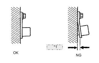
*1 Clearance
-
Check the camshaft position sensor installation.
OK The camshaft position sensor is installed properly.
NG
SECURELY REINSTALL SENSOR Click here
OK
-
-
INSPECT CAMSHAFT TIMING GEAR ASSEMBLY (SENSOR PLATE TOOTH)
-
Check the teeth of the sensor plate.
OK Sensor plate teeth do not have any cracks or deformation.
NG
REPLACE CAMSHAFT TIMING GEAR ASSEMBLY Click here
OK
-
-
REPLACE CAMSHAFT POSITION SENSOR
-
Replace the camshaft position sensor Click here.
NEXT
-
-
CHECK WHETHER DTC OUTPUT RECURS
-
Connect the GTS to the DLC3.
-
Turn the engine switch on (IG).
-
Turn the GTS on.
-
Clear DTCs Click here.
-
Drive the vehicle in accordance with the driving pattern described in Confirmation Driving Pattern.
-
Read DTCs.
Result Result Proceed to No DTC is output A P1340, P1342 and/or P1343 is output B Tech Tips
If the engine does not start, replace the ECM.
A
END
B
REPLACE ECM Click here
-