| DTC Code | DTC Name |
|---|---|
| Fuel Injector Circuit |
DESCRIPTION
The fuel injector assemblies are located on the intake manifold. They inject fuel into the cylinders based on the signals from the ECM.
CAUTION / NOTICE / HINT
Inspect the fuses for circuits related to this system before performing the following inspection procedure.
PROCEDURE
- Click here
CHECK FUEL INJECTOR ASSEMBLY (POWER SOURCE)
-
Disconnect the fuel injector assembly connector.
-
Turn the ignition switch to ON.
-
Measure the voltage according to the value(s) in the table below.
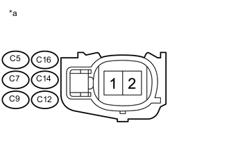
Standard Voltage Cylinder Tester Connection Switch Condition Specified Condition No. 1 C5-1 - Body ground Ignition switch ON 11 to 14 V No. 2 C16-1 - Body ground Ignition switch ON 11 to 14 V No. 3 C7-1 - Body ground Ignition switch ON 11 to 14 V No. 4 C14-1 - Body ground Ignition switch ON 11 to 14 V No. 5 C9-1 - Body ground Ignition switch ON 11 to 14 V No. 6 C12-1 - Body ground Ignition switch ON 11 to 14 V Table 1. Text in Illustration *a Front view of wire harness connector
(to Fuel Injector Assembly)
-
Turn the ignition switch off.
- OKClick here
- NG
REPAIR OR REPLACE HARNESS OR CONNECTOR (INTEGRATION RELAY (IG2) - FUEL INJECTOR ASSEMBLY)
-
- Click here
INSPECT FUEL INJECTOR ASSEMBLY
-
Inspect the fuel injector assembly (Click here).
- OKClick here
- NG
REPLACE FUEL INJECTOR ASSEMBLY (Click here)
-
- Click here
CHECK HARNESS AND CONNECTOR (FUEL INJECTOR ASSEMBLY - ECM)
-
Disconnect the fuel injector assembly connector.
-
Disconnect the ECM connector.
-
Measure the resistance according to the value(s) in the table below.
Standard Resistance Table 2. for LHD Cylinder Tester Connection Condition Specified Condition No. 1 C5-2 - Body ground Always 10 kΩ or higher C5-2 - C45-86 (#10) Always Below 1 Ω No. 2 C16-2 - Body ground Always 10 kΩ or higher C16-2 - C45-109 (#20) Always Below 1 Ω No. 3 C7-2 - Body ground Always 10 kΩ or higher C7-2 - C45-85 (#30) Always Below 1 Ω No. 4 C14-2 - Body ground Always 10 kΩ or higher C14-2 - C45-108 (#40) Always Below 1 Ω No. 5 C9-2 - Body ground Always 10 kΩ or higher C9-2 - C45-84 (#50) Always Below 1 Ω No. 6 C12-2 - Body ground Always 10 kΩ or higher C12-2 - C45-107 (#60) Always Below 1 Ω Table 3. for RHD Cylinder Tester Connection Condition Specified Condition No. 1 C5-2 - Body ground Always 10 kΩ or higher C5-2 - C46-86 (#10) Always Below 1 Ω No. 2 C16-2 - Body ground Always 10 kΩ or higher C16-2 - C46-109 (#20) Always Below 1 Ω No. 3 C7-2 - Body ground Always 10 kΩ or higher C7-2 - C46-85 (#30) Always Below 1 Ω No. 4 C14-2 - Body ground Always 10 kΩ or higher C14-2 - C46-108 (#40) Always Below 1 Ω No. 5 C9-2 - Body ground Always 10 kΩ or higher C9-2 - C46-84 (#50) Always Below 1 Ω No. 6 C12-2 - Body ground Always 10 kΩ or higher C12-2 - C46-107 (#60) Always Below 1 Ω
- OK
REPLACE ECM (Click here)
- NG
REPAIR OR REPLACE HARNESS OR CONNECTOR
-