SFI SYSTEM, Diagnostic DTC:P0416, P0417
| DTC Code | DTC Name |
|---|---|
| P0416 | Secondary Air Injection System Switching Valve "B" Circuit Open |
| P0417 | Secondary Air Injection System Switching Valve "B" Circuit Shorted |
DESCRIPTION
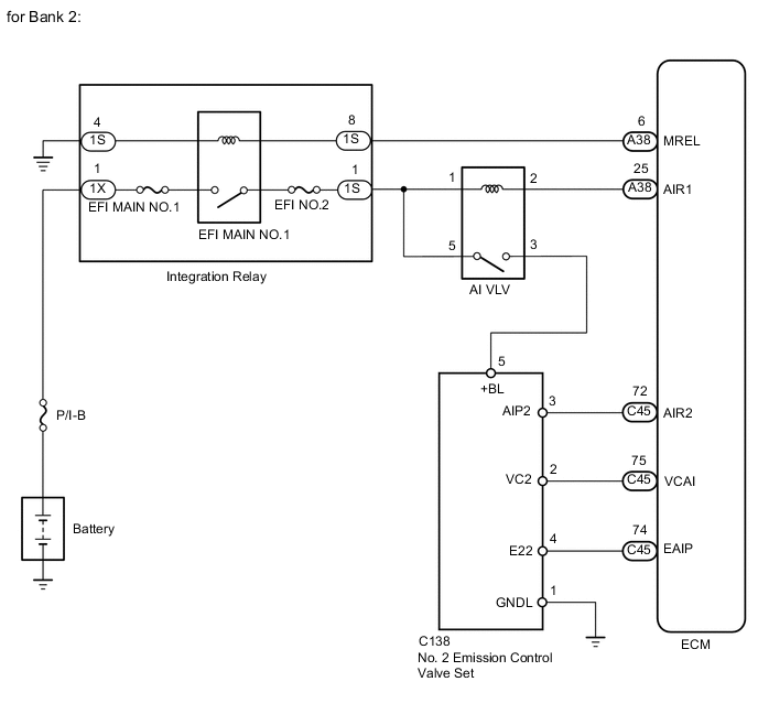
The ECM operates the air injection VSV relay (AI VLV) which causes the No. 2 emission control valve to operate.
| DTC No. | DTC Detection Condition | Trouble Area |
|---|---|---|
| P0416 | Open or short in the air injection VSV relay (AI VLV) circuit for 3 seconds (1 trip detection logic). |
|
| P0417 | Open or short in the air injection VSV relay (AI VLV) circuit for 3 seconds (1 trip detection logic). |
|
MONITOR DESCRIPTION
These DTCs are designed to detect a malfunction in the air injection VSV (AI VLV) relay circuit. When the system is normal, the battery voltage is applied to terminal AIR1 of the ECM while the air injection VSV (AI VLV) relay is turned off, and the battery voltage is not applied to terminal AIR1 of the ECM while the air injection VSV (AI VLV) relay is turned on. The ECM illuminates the MIL and stores a DTC when either one of the following conditions is detected.
-
The battery voltage is not applied to terminal AIR1 while the air injection VSV (AI VLV) relay is off.
-
The battery voltage is applied to terminal AIR1 while the air injection VSV (AI VLV) relay is on.
WIRING DIAGRAM
CAUTION / NOTICE / HINT
Note
Inspect the fuses of circuits related to this system before performing the following inspection procedure.
Tech Tips
Read freeze frame data using the GTS. Freeze frame data records the engine condition when malfunctions are detected. When troubleshooting, freeze frame data can help determine if the vehicle was moving or stationary, if the engine was warmed up or not, if the air-fuel ratio was lean or rich, and other data from the time the malfunction occurred.
PROCEDURE
-
INSPECT AIR INJECTION VSV RELAY (AI VLV)
-
Inspect the air injection VSV relay (AI VLV) Click here.
NG 
REPLACE AIR INJECTION VSV RELAY (AI VLV)
OK 
-
-
CHECK AIR INJECTION VSV RELAY (AI VLV) (POWER SOURCE)
-
Remove the air injection VSV relay (AI VLV).
-
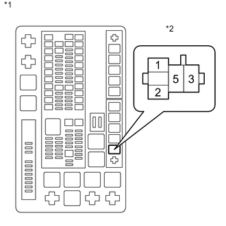
Text in Illustration *1 Engine Room Relay Block *2 Air Injection VSV Relay (AI VLV) Measure the voltage according to the value(s) in the table below.
Standard Voltage Tester Connection Condition Specified Condition Air injection VSV relay (AI VLV) terminal 1 - Body ground Ignition switch ON 11 to 14 V Air injection VSV relay (AI VLV) terminal 5 - Body ground Ignition switch ON 11 to 14 V
NG
REPAIR OR REPLACE HARNESS OR CONNECTOR
OK
-
-
CHECK HARNESS AND CONNECTOR (ECM - AIR INJECTION VSV RELAY (AI VLV))
-
Remove the air injection VSV relay (AI VLV).
-
Disconnect the ECM connector.
-
Measure the resistance according to the value(s) in the table below.
Standard Resistance Tester Connection Condition Specified Condition Air injection VSV relay (AI VLV) terminal 2 - A38-25 (AIR1) Always Below 1 Ω Air injection VSV relay (AI VLV) terminal 2 or A38-25 (AIR1) - Body ground Always 10 kΩ or higher
OK
REPLACE ECM Click here
NG
REPAIR OR REPLACE HARNESS OR CONNECTOR
-