REPAIR INSTRUCTION INITIALIZATION
-
PROCEDURES NECESSARY WHEN CABLE IS DISCONNECTED/RECONNECTED TO BATTERY TERMINAL
Procedures Necessary when Cable is Disconnected/Reconnected to Battery Terminal Necessary Procedure Procedure Details Effect or Inoperative Function when Necessary Procedure is not Performed Notes Initialize parking assist monitor system
-
Fully turn the steering wheel to the right and left.
-
Drive the vehicle at more than 20 km/h (12 mph) for more than 5 minutes on a straight road with as little traffic congestion as possible.
Perform either of the following procedures.
Parking assist function - Initialization of power back door system Completely close the back door by hand once. Power back door function Initialization is not necessary if the cable is disconnected and reconnected to the negative (-) battery terminal while the back door is closed. However, the power back door system will not operate if the back door is not unlocked after the cable is reconnected. Note
After the engine switch is turned off, the multi-media module receiver assembly records various types of memory and settings. As a result, after turning the engine switch off, make sure to wait at least a minute before disconnecting the cable from the negative (-) battery terminal.
-
-
PROCEDURES NECESSARY WHEN ECU OR OTHER PARTS ARE REPLACED
Procedures Necessary when ECU or Other Parts are Replaced Replacement Part Necessary Procedures Effects / Inoperative Functions When Necessary Procedures are not Performed Notes ECM (1UR-FE) Register VIN. DTC P0630 is output. - ECM (1VD-FTV, w/ DPF)
-
Learning values save
-
Learning values write
Engine starting - Engine assembly (1VD-FTV, w/ DPF)
-
Clear Crank Time Compensation Data
-
Injector compensation code registration
-
Pilot quantity learning
Engine starting - Crankshaft position sensor plate (1VD-FTV, w/ DPF) Clear crank time compensation data Crank time compensation data compensation amount is same as before replacement, affecting crank time compensation data - Air fuel ratio sensor (1VD-FTV, w/ DPF) Clear A/F sensor compensation data EGR volume is affected - Fuel supply pump (1VD-FTV, w/ DPF) Supply pump initialization Engine startability - 1VD-FTV, w/ DPF
-
Front exhaust pipe assemblies (DPF catalytic converter)
-
Monolithic converter assemblies (CCo catalytic converter)
-
Clear DPF thermal deterioration data
-
Learning values write
Even if catalytic converter is replaced with new one, catalyst record of DPF thermal deterioration stored in ECM is same as before replacement - Fuel injector (1VD-FTV, w/ DPF)
-
Injector compensation code registration
-
Pilot quantity learning
DTC P062F is output - Fuel injector (1VD-FTV, w/o DPF) Injector compensation code registration DTC P1601 is output - Fuel supply pump (1VD-FTV, w/o DPF) ECM initialization Engine starting - ECM (1VD-FTV, w/o DPF) ECU communication ID registration Engine starting - Distance control ECU Initialization Cannot adjust millimeter wave radar sensor - Millimeter wave radar sensor assembly Adjusting the radar beam axis Dynamic radar cruise control system does not operate normally - Any of shift solenoid valves Reset memory Large shift shock - Transmission wire Add and adjust the ATF level Automatic transmission assembly damaged - Valve body assembly Add and adjust the ATF level Automatic transmission assembly damaged - Reset memory Large shift shock - Oil cooler and oil cooler tube Add and adjust the ATF level Large shift shock - Park/neutral position switch Adjust the park/neutral position switch
-
Back-up light does not turn on
-
Meter indicator display malfunction
-
Vehicle undrivable
-
Shifting not possible
- Transmission floor shift assembly Adjust the shift lever position
-
Back-up light does not turn on
-
Meter indicator display malfunction
-
Vehicle undrivable
-
Shifting not possible
- Automatic transmission assembly Add and adjust the ATF level Automatic transmission assembly damaged - Reset memory Large shift shock - Automatic transmission fluid (for AB60F, 3UR-FE) ATF thermal degradation estimate reset The value of the Data List item "ATF Thermal Degradation Estimate" is not estimated correctly. -
-
Clutch pedal (for LHD)
-
Clutch master cylinder (for LHD)
Inspect and adjust clutch pedal
-
Clutch slips
-
Clutch dies not disengage
-
-
Clutch pedal (for RHD)
-
Clutch master cylinder (for RHD)
Inspect and adjust clutch pedal
-
Clutch slips
-
Clutch dies not disengage
- Suspension control ECU Vehicle height offset calibration Vehicle height sensor date may be affected due to installation position, or vehicle height recognition may be erroneous After vehicle height offset calibration is performed, it is necessary to calibrate the yaw rate sensor Height control sensor Vehicle height offset calibration Vehicle height sensor date may be affected due to installation position, or vehicle height recognition may be erroneous After vehicle height offset calibration is performed, it is necessary to calibrate the yaw rate sensor
-
Suspension
-
Underbody components
-
Steering angle neutral point in memory
-
Yaw rate and G sensor zero point calibration
-
The brake control and dynamic control systems do not operate properly
-
VGRS system
-
Parking assist monitor system
Removed/installed or replaced Tire pressure warning ECU and receiver
-
Register transmitter IDs
-
Initialize tire pressure warning system
-
When DTC detection conditions of "transmitter ID not received" DTC is met, tire pressure warning light blinks for 1 minute, and then illuminates
-
Tire pressure monitoring function
- Tire pressure warning valve and transmitter
-
Register transmitter IDs
-
Initialize tire pressure warning system
-
When DTC detection conditions of "transmitter ID not received" DTC is met, tire pressure warning light blinks for 1 minute, and then illuminates
-
Tire pressure monitoring function
Even if only one wheel is replaced, IDs for all 5 wheels must be registered. Skid control ECU (Master cylinder solenoid) Deceleration sensor zero point calibration The brake control system does not operate properly - Deceleration sensor
-
Clearing zero point calibration data
-
Deceleration sensor sensor zero point calibration
The brake control system does not operate properly - Skid control ECU (Master cylinder solenoid)
-
Clearing zero point calibration data
-
Yaw rate and acceleration sensor zero point calibration
The brake control and dynamic control systems do not operate properly - Yaw rate sensor assembly
-
Clearing zero point calibration data
-
Yaw rate and acceleration sensor zero point calibration
The brake control and dynamic control systems do not operate properly - Vehicle height adjustment
-
Clearing zero point calibration data
-
Yaw rate and acceleration sensor zero point calibration
-
Steering sensor initialization
The brake control and dynamic control systems do not operate properly w/ active height control system
-
Brake pedal
-
Hydraulic brake booster
Check brake pedal height
-
Brake performance problem
-
Delayed stop light illumination or continuous illumination
-
-
Parking brake lever
-
Parking brake cable
-
Parking brake assembly
Adjust parking brake lever travel
-
Brake drag
-
Brake performance problem
-
Delayed stop light illumination or continuous illumination
-
-
Steering control ECU
-
Steering column
-
Steering intermediate shaft
-
Steering actuator assembly
Calibration
-
VGRS system
-
DTC output
- Steering angle sensor Initialization
-
VGRS system
-
Other related systems cannot operate properly
- Steering column Steering off center adjustment Steering system does not operate normally - Multi-media module receiver assembly (w/ G-BOOK system) Vehicle contract setting G-BOOK service If the multi-media module receiver assembly is replaced on vehicles that do not have a contract for the G-BOOK service, perform the vehicle contract setting. Rear television camera Rear television camera optional axis (Camera position setting) Vehicle width extension lines and expected course are deviated Replace or installation angle of the rear television camera changes because of the removal and installation of the rear television camera Side television camera Side television camera optional axis (Camera position setting) Vehicle parallel lines and expected course are deviated Replace or installation angle of the side television camera changes because of the removal and installation of the side television camera Parking assist ECU
-
Steering angle neutral point in memory
-
Store the left and right maximum steering angles
-
Rear television camera optical axis (Camera position setting)
-
Side television camera optical axis (Camera position setting)
Parking assist monitor system Replace or installation angle of the rear television camera changes because of the removal and installation of the rear television camera w/ Entry and Start System:
-
ID code box
-
Steering lock ECU
-
Key
-
Certification ECU
Registration
-
Wireless door lock operation
-
Entry operation
-
Engine starting
-
Steering unlock
Refer to the Service Bulletin for the registration procedure. w/o Entry and Start System:
-
Transponder key ECU
-
ECM
-
Key
Registration Engine starting Refer to the Service Bulletin for the registration procedure. w/o Entry and Start System:
-
Door control transmitter
-
Door control receiver
Register recognition code Wireless door lock operation - Servo motors Servomotors initialization Air conditioning system does not operate properly During initialization, the AUTO indicator light comes on, and then goes off when initialization has finished. for Models with Jam Protection Function on 4 Windows:
-
Front Power window regulator motor LH
-
Front Power window regulator motor RH
-
Rear Power window regulator motor LH
-
Rear Power window regulator motor RH
Initialize the motor
-
Auto Operation
-
Jam protection function
-
Power window control system (for Models with Jam Protection Function on 4 Windows)
- for Models with Jam Protection Function on Driver Door Window Only:
-
Front Power window regulator motor LH (for LHD)
-
Front Power window regulator motor RH (for RHD)
Initialize the motor
-
Auto Operation
-
Jam protection function
-
Power window control system (for Models with Jam Protection Function on Driver Door Window Only)
- Inner rear view mirror
-
Compass zone setting
-
Compass calibration
-
Register transmitter code
Direction is not displayed correctly -
-
Sliding roof driver gear (Sliding roof ECU)
-
Sliding roof glass
Initialize sliding roof system
-
Auto operation
-
Jam protection function
-
Sliding roof operation after engine switch OFF
-
Wireless door lock control function
-
Key-linked operation function (Driver side door only)
-
Entry lock switch-linked operation
-
-
Power back door unit
-
Back door lock
Initialize back door system Power back door system - w/ Static Headlight Auto Leveling
-
Headlight leveling ECU
-
Height control sensor LH
Initialization Headlight leveling function - w/ Dynamic Headlight Auto Leveling, w/o Active Height Control Suspension
-
Headlight swivel ECU
-
Height control sensor LH
Initialization Headlight leveling function - Headlight assembly Adjustment Beam axis deviation - Fog light assembly Adjustment Beam axis deviation - Front bumper Adjustment Beam axis deviation - -
-
REGISTRATION RELATED TO ECD SYSTEM (w/ DPF)
-
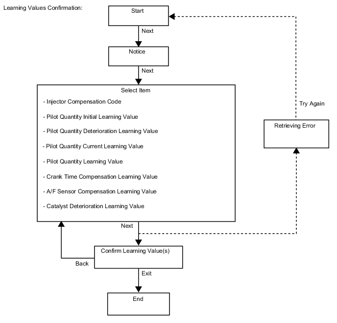
LEARNING VALUES CONFIRMATION
This procedure uses the GTS to display the learned values (injector compensation code, pilot quantity initial learning value, pilot quantity deterioration learning value, pilot quantity current learning value, pilot quantity learning value, crank time compensation learning value, A/F sensor learning value and catalyst deterioration learning value) stored in the ECM.
Tech Tips
-
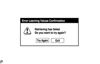
A malfunction may occur when reading the values if there is a problem with the ECM, a wire harness or the connection to the DLC3. If the wire harnesses and the connection to the DLC3 are inspected and found to be normal, the ECM may be malfunctioning.
-
Connect the GTS to the DLC3.
-
Turn the engine switch on (IG) and turn the GTS on.
Note
Do not start the engine.
-
Enter the following menus: Engine and ECT / Utility / Learning values confirmation.
-
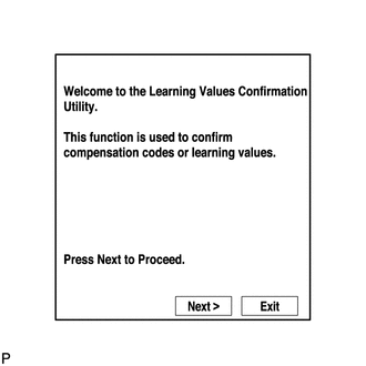
Press "Next".
-
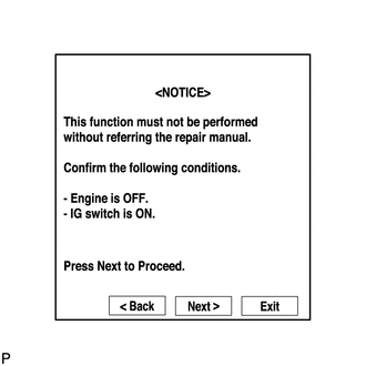
Press "Next" again to proceed.
-
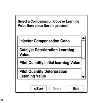
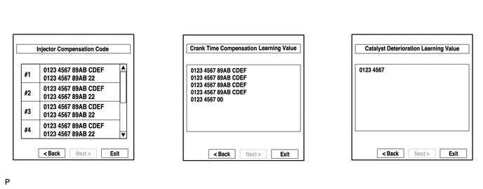
Select the value to confirm and press "Next".
-
When the next screen is displayed, confirm the contents and press "Exit".
-
-
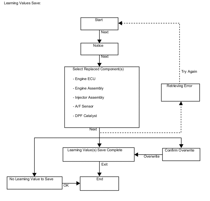
LEARNING VALUES SAVE
This procedure uses the GTS to save the learned values (injector compensation code, pilot quantity learning value, crank time compensation learning value, catalyst deterioration learning value and A/F sensor learning value) stored in the ECM in the GTS depending on the components being replaced.
Tech Tips
-
When replacing the engine assembly, injector assembly, front exhaust pipe assemblies (DPF catalytic converter) or the A/F sensor together with the ECM, this function automatically determines the data which can be transferred (old data) and saves the data in the GTS.
-
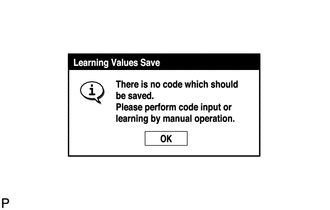
When there is no data to read from the ECM, manually perform the procedure to register each compensation code and learning value in the ECM.
-
A malfunction may occur when reading the values if there is a problem with the ECM, a wire harness or the connection to the DLC3. If the wire harnesses and the connection to the DLC3 are inspected and found to be normal, the ECM may be malfunctioning.
-
Connect the GTS to the DLC3.
-
Turn the engine switch on (IG) and turn the GTS on.
Note
Do not start the engine.
-
Enter the following menus: Engine and ECT / Utility / Learning values save.
-
Press "Next".
-
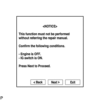
Press "Next" again to proceed.
-
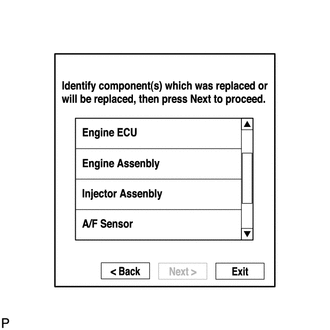
Select any components being replaced and press "Next". If no applicable components are displayed, press "Next" without selecting anything.
-
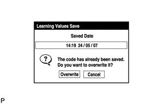
If the overwrite confirmation screen is displayed, press "Overwrite".
-
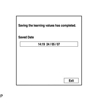
When the operation is finished, confirm the date and time of the save operation, and press "Exit".
-
-
LEARNING VALUES WRITE
This procedure uses the GTS to write all of the learned values (injector compensation code, pilot quantity learning value, crank time compensation learning value, catalyst deterioration learning value and A/F sensor learning value) stored in the GTS to the ECM.
Tech Tips
-
A malfunction may occur when writing the values if there is a problem with the ECM, a wire harness or the connection to the DLC3. If the wire harnesses and the connection to the DLC3 are inspected and found to be normal, the ECM may be malfunctioning.
-
Connect the GTS to the DLC3.
-
Turn the engine switch on (IG) and turn the GTS on.
Note
Do not start the engine.
-
Enter the following menus: Engine and ECT / Utility / Learning values write.
-
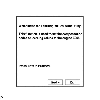
Press "Next".
-

Press "Next" again to proceed.
-
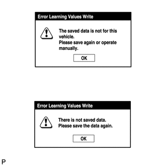
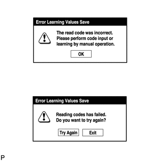
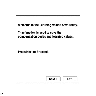
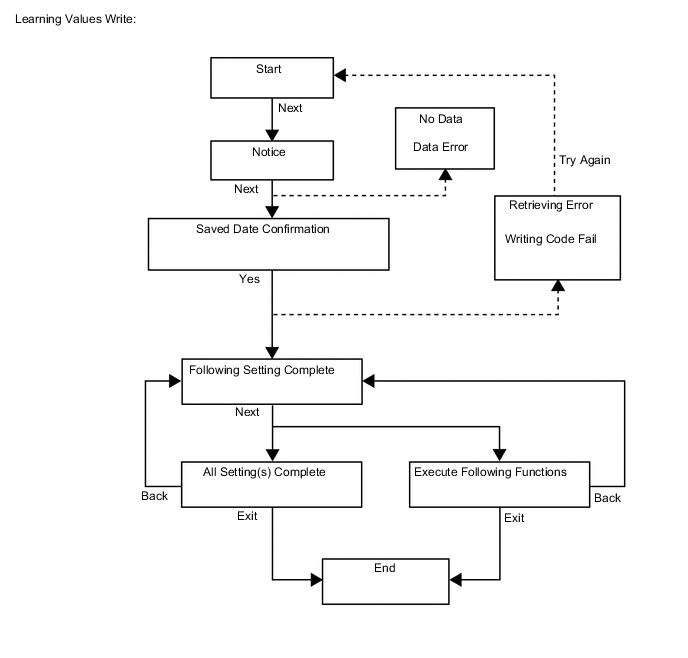
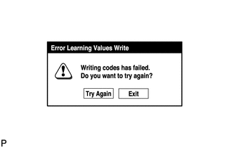
If the "Error Learning Values Write" screen indicating a problem with the saved value(s) or an absence of saved values is displayed, perform "Learning Values Save" again.
-
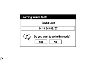
Confirm the date and time of the save operation, and then press "Yes".
-
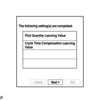
Confirm the contents, and then press "Next".
-
If any instructions are displayed on the GTS, manually perform the procedure to register each applicable compensation code or learning value in the ECM.
-
Clear the DTCs.
-
-
INPUT INJECTOR COMPENSATION CODE(S) INTO ECM
Note
-
When an injector assembly is replaced, the new injector compensation code must be input into the ECM. When the ECM is replaced, all of the existing injector compensation codes must be input into the new ECM.
-
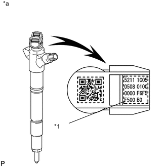
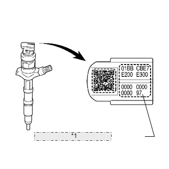
Injector compensation codes are unique, 30-digit, alphanumeric values printed on the head portion of each injector assembly. If an incorrect injector compensation code is input into the ECM, the engine assembly may rattle or engine idling may become rough. In addition, engine failure may occur and the life of the engine may be shortened.
-
When an injector compensation code is input into the ECM, the pilot quantity learning values stored in the ECM are initialized. Also, DTC P062F is stored when the pilot quantity learning values are initialized.
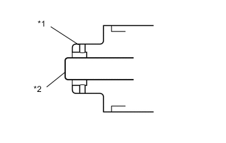
Text in Illustration *1 Injector Compensation Code *a Example
-
After replacing injector assemblies with new one(s), input injector compensation code(s) of the injector assemblies into the ECM as follows:
Tech Tips
-
Each injector assembly has different fuel injection characteristics. In order to optimize the fuel injections, the ECM uses the compensation codes to balance the different fuel injections between each injector assembly.
-
When only one or more injector assemblies are replaced, input the injector compensation code(s), perform pilot quantity learning, and then clear the DTCs.
-
When the engine switch is turned on (IG) after replacing the ECM, DTC P062F is stored. This indicates that the injector compensation code(s) need to be registered. Manually clear the DTC upon completion of pilot quantity learning.
-
Input the compensation code(s), which is/are imprinted on the head portion(s) of the new injector assemblies, into the GTS.
-
Input the new injector compensation code(s) into the ECM using the GTS.
-
Turn the GTS off and turn the engine switch off.
-
Wait for at least 30 seconds.
-
Turn the engine switch on (IG) and turn the GTS on.
-
Perform pilot quantity learning.
-
Clear DTC P062F stored in the ECM using the GTS.
Note
If the DTCs are cleared without performing pilot quantity learning, DTC P062F is stored immediately after clearing DTCs.
-
-
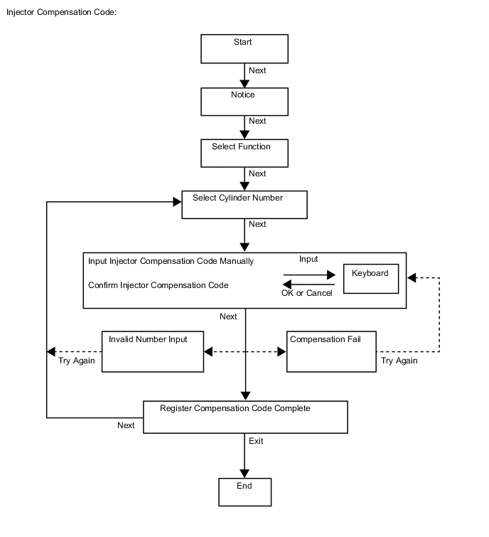
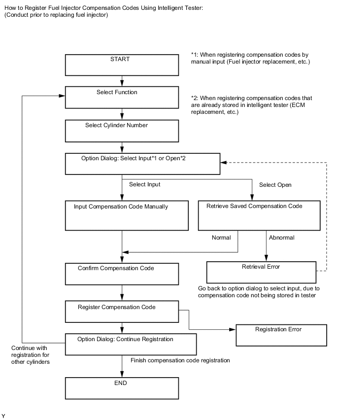
Register compensation codes.
-
Connect the GTS to the DLC3.
-
Turn the engine switch on (IG).
Note
Do not start the engine.
-
Turn the GTS on.
-
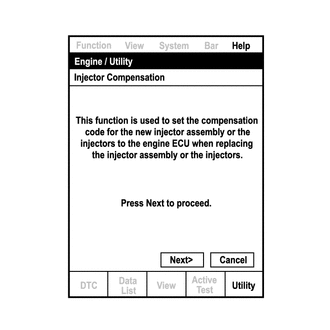
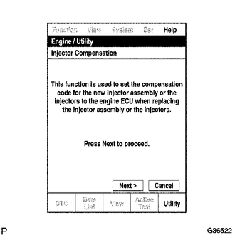
Enter the following menus: Engine and ECT / Utility / Injector Compensation.
-
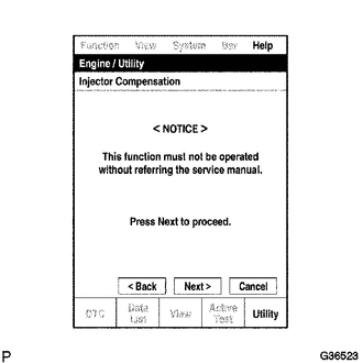
Press Next.
-
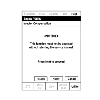
Press Next again to proceed.
-
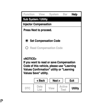
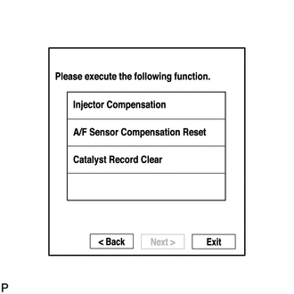
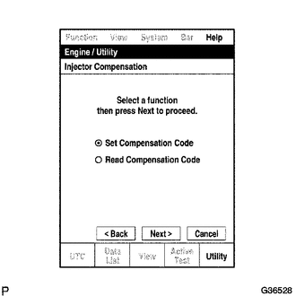
Select "Set Compensation Code".
-
Press Next.
-
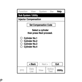
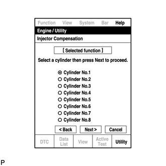
Select the number of the cylinder corresponding to the injector compensation code that you want to register.
-
Press Next.
-
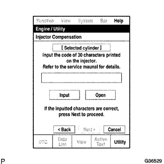
Register compensation code.
-
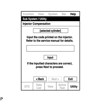
Press Input.
-
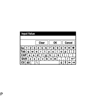
Manually input the cylinder compensation code using the keyboard on the GTS screen. The code is a 30-digit, alphanumeric value printed on the injector head portion.
Tech Tips
Each injector compensation code is unique. The compensation code for each selected cylinder must be input into the GTS correctly.
-
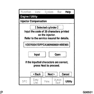
Confirm that the compensation code for the selected cylinder is correct, and then press OK.
-
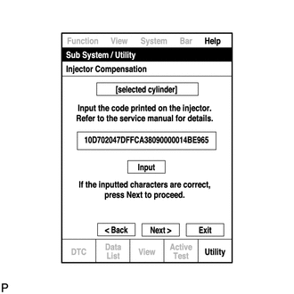
Check that the compensation code displayed on the screen is correct by comparing it with the 30-digit alphanumeric value on the head portion of the injector assembly.
Note
If an incorrect injector compensation code is input into the ECM, the engine may rattle or engine idling may become rough. In addition, engine failure may occur and the life of the engine may be shortened.
Tech Tips
-
If a wrong compensation code is input or read, return to the Input Value screen by pressing Input.
-
The saving process may fail due to a problem with the wire harness or a bad connection with the DLC3. Check the wire harness and DLC3 connection. If no problem is found with either, the ECM may be malfunctioning. Check the ECM and repeat this operation.
-
-
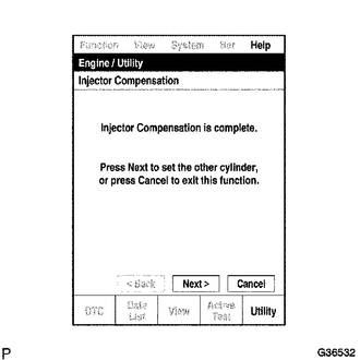
Press Next to register the injector compensation code in the ECM.
Tech Tips
-
If the registration process fails, the injector compensation code may be incorrect. Check the injector compensation code again.
-
If the input injector compensation code fails to register even though it is input correctly, there may be a problem with the wire harness or a bad connection with the DLC3. Check the wire harness and DLC3 connection. If no problem is found with either, the ECM may be malfunctioning. Check the ECM and restart this operation.
-
-
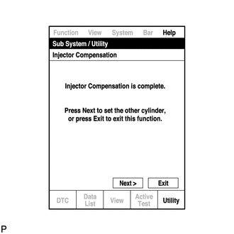
If you want to continue with other compensation code registrations, press Next. To finish the registration, press Exit.
-
Turn the GTS off and turn the engine switch off.
-
Wait for at least 30 seconds.
-
Turn the engine switch on (IG), and then turn the GTS on.
-
Perform pilot quantity learning.
-
Clear DTC P062F stored in the ECM using the GTS.
Note
If the DTCs are cleared without performing pilot quantity learning, DTC P062F is stored immediately after clearing DTCs.
-
-
-
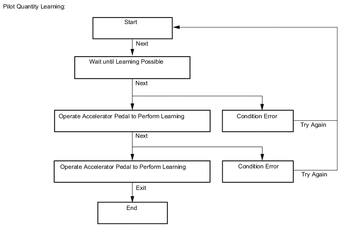
PILOT QUANTITY LEARNING
-
"Pilot Quantity Learning" is performed when injector assemblies have been replaced and injector compensation codes have been registered. "Pilot Quantity Learning (Detail)" is performed when there are engine problems but no DTCs are output and the technician wishes to clear the learned values and have the vehicle relearn the values.
-
This procedure uses the GTS to perform "Pilot Quantity Learning".
-
When replacing the injector assembly, engine or ECM, perform this procedure after performing injector compensation (manual ID code registration).
Note
After completing this procedure, clear the DTCs using the GTS.
Tech Tips
-
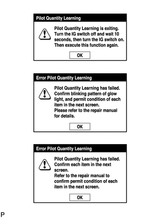
If "Exit" is pushed during the step where the accelerator pedal is operated and "Pilot Quantity Learning" is canceled, turn the engine switch off, wait 10 seconds, check the vehicle condition, and then perform learning again.
-
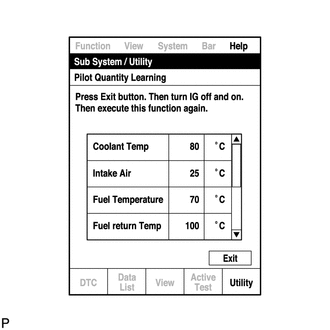
If an error occurs during learning, check the vehicle condition after turning the engine switch off, and then perform learning again.
-
If learning is canceled and DTCs are output due to excessive racing of the engine (depressing the accelerator pedal for 2 seconds or more), turn the engine switch off, and then perform learning again.
-
A communication malfunction may occur if there is a problem with the ECM, a wire harness or the connection to the DLC3. If the wire harnesses and the connection to the DLC3 are inspected and found to be normal, the ECM may be malfunctioning.
-
-
Connect the GTS to the DLC3.
-
Start the engine.
-
Turn the GTS on.
-
Enter the following menus: Engine and ECT / Utility / Pilot quantity learning.
-
Press "Next".
-
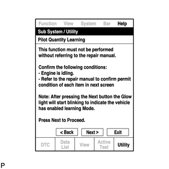
Press "Next" again to proceed.
-
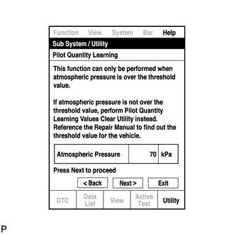
Confirm that the atmospheric pressure screen is displayed.
-
Confirm the displayed atmospheric pressure.
Standard Atmosphere Pressure is 87 kPa or more Note
-
If the atmospheric pressure is below the standard range, "Pilot Quantity Learning" cannot be performed. In this case, press "Exit" and clear the learned values using "Pilot Quantity Learning Value Clear".
-
If the atmospheric pressure is below the standard range, even if "Pilot Quantity Learning" is performed, learning will not be completed.
-
-
If the atmospheric pressure is within the standard range, proceed to the next screen.
-
-
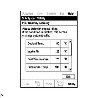
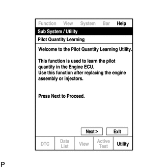
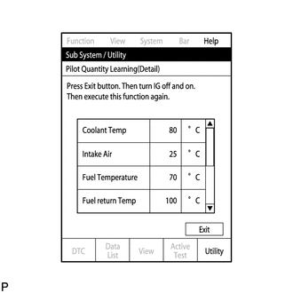
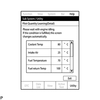
Confirm the condition of the engine and wait until learning can be performed.
Essential Conditions for Learning GTS Display Standard Coolant Temp 70 to 96°C Intake Air -2 to 120°C Fuel Temperature 30 to 90°C Battery Voltage 10 V or higher Pilot Quantity State (CAT) READY Tech Tips
-
If the values deviate from the standard above, "Pilot Quantity Learning" enters a standby state or is canceled.
-
When the display indicates that "Pilot Quantity State (CAT)" is prohibited, perform "Pilot Quantity Learning" after performing the "Activate the DPF Rejuvenate (PM)" Active Test using the GTS.
-
When the essential conditions to perform learning are met, the screen will change automatically.
Note
-
If "Activate the DPF Rejuvenate (PM)" is performed after an injector compensation code is input but before "Pilot Quantity Learning" is performed, DTC P062F is stored and the MIL illuminates due to "Pilot Quantity Learning" being incomplete.
-
Using the GTS, make sure that DTCs other than DTC P062F are not output.
-
If DTCs other than DTC P062F are output, perform troubleshooting for those DTCs, and then perform "Activate the DPF Rejuvenate (PM)".
Tech Tips
DTC P062F is stored when the value registered in the ECM for an input injector compensation code, catalyst deterioration learning value and/or pilot quantity deterioration learning value is the initial value.
-
-
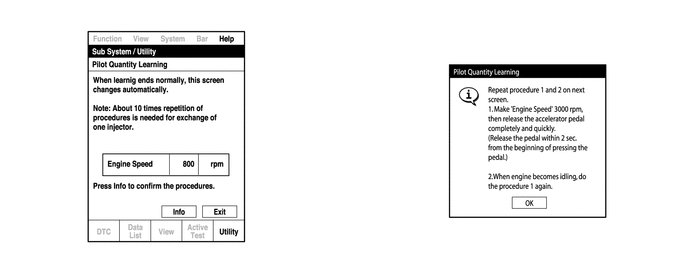
Follow the prompts on the screen and repeat the following procedure until the screen changes: Starting with the engine idling, race the engine until the engine speed is 3000 rpm or more for no more than 2 seconds, and then let the engine return to idling.
Tech Tips
-
After confirming that the engine speed has reached 3000 rpm, completely release the accelerator pedal in order for the throttle opening amount to become 0%.
-
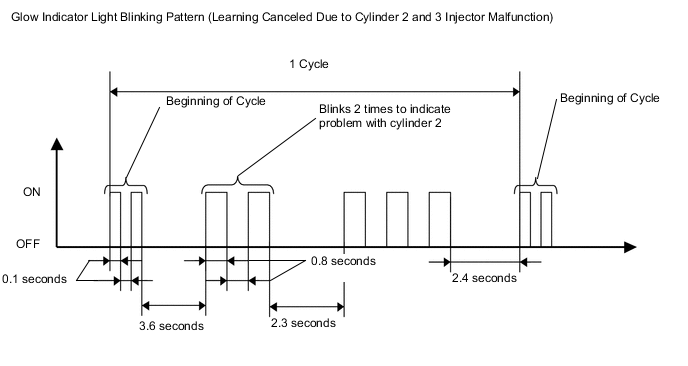
It is possible to confirm the status of the learning operation during "Pilot Quantity Learning" by observing the blinking pattern of the glow indicator light.
Glow Indicator Light Blinking Pattern Learning Status Glow Indicator Light Condition Conditions essential to start learning have not been met Blinking at 0.5 second intervals Conditions essential to start learning have been met Blinking at 1 second intervals During racing (learning is being performed) Blinking at 1 second intervals Learning is finished Off Learning has been canceled Blinking at 1.5 second intervals Learning has been canceled (malfunctioning cylinder is indicated by blinking pattern) Blinking at 0.8 second intervals (2.3 second intervals between each set of blinks representing the number of a malfunctioning cylinder) 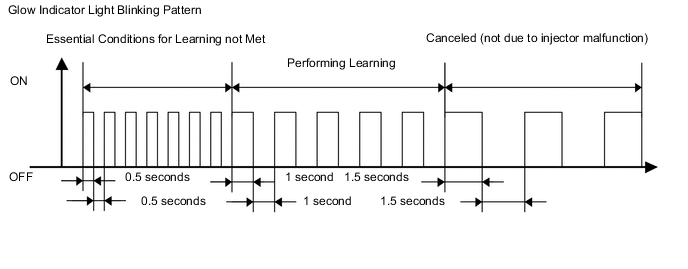
-
-
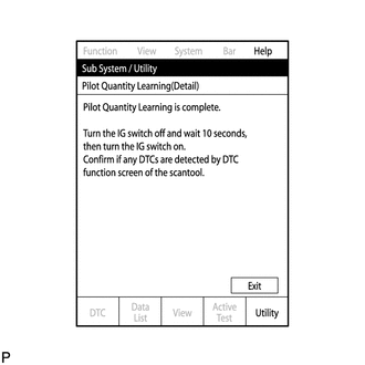
When the screen changes, push "Exit".
-
Turn the GTS off and turn the engine switch off.
-
Wait for at least 10 seconds.
-
Turn the engine switch on (IG), and then turn the GTS on.
-
Clear the DTCs.
-
Turn the engine switch off.
Note
Do not disconnect the cable from the negative (-) battery terminal for 30 seconds after turning the engine switch off.
Tech Tips
-
The main relay turns off after the learned value is stored in the ECM.
-
The main relay turns off within approximately 5 to 10 seconds of turning the engine switch off.
-
-
-
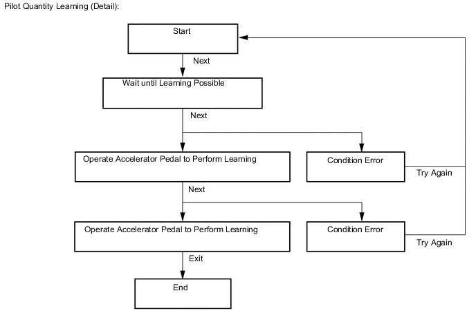
PILOT QUANTITY LEARNING (DETAIL)
-
"Pilot Quantity Learning" is performed when injector assemblies have been replaced and injector compensation codes have been registered. "Pilot Quantity Learning (Detail)" is performed when there are engine problems but no DTCs are output and the technician wishes to clear the learned values and have the vehicle relearn the values.
It takes time to clear the learned values and perform learning for all cylinders.
-
This procedure uses the GTS to perform "Pilot Quantity Learning (Detail)".
-
When replacing the injector assembly, engine or ECM, perform this procedure after performing injector compensation (manual ID code registration).
Note
After completing this procedure, clear the DTCs using the GTS.
Tech Tips
-
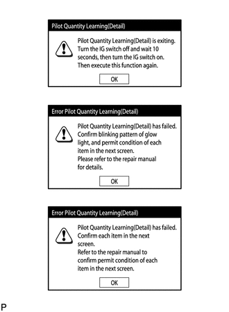
If "Exit" is pushed during the step where the accelerator pedal is operated and "Pilot Quantity Learning (Detail)" is canceled, turn the engine switch off, wait 10 seconds, check the vehicle condition, and then perform learning again.
-
If an error occurs during learning, check the vehicle condition after turning the engine switch off, and then perform learning again.
-
If learning is canceled and DTCs are output due to excessive racing of the engine (depressing the accelerator pedal for 2 seconds or more), turn the engine switch off, and then perform learning again.
-
A communication malfunction may occur if there is a problem with the ECM, a wire harness or the connection to the DLC3. If the wire harnesses and the connection to the DLC3 are inspected and found to be normal, the ECM may be malfunctioning.
-
Connect the GTS to the DLC3.
-
Start the engine.
-
Turn the GTS on.
-
Enter the following menus: Engine and ECT / Utility / Pilot quantity learning (Detail).
-
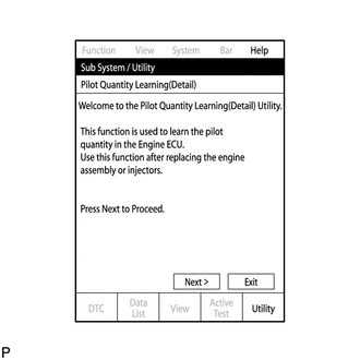
Press "Next".
-
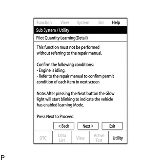
Press "Next" again to proceed.
-
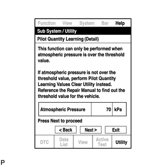
Confirm that the atmospheric pressure screen is displayed.
-
Confirm the displayed atmospheric pressure.
Standard Atmosphere Pressure is 87 kPa or more Note
-
If the atmospheric pressure is below the standard range, "Pilot Quantity Learning" cannot be performed. In this case, press "Exit" and clear the learned values using "Pilot Quantity Learning Value Clear".
-
If the atmospheric pressure is below the standard range, even if "Pilot Quantity Learning" is performed, learning will not be completed.
-
-
If the atmospheric pressure is within the standard range, proceed to the next screen.
-
-
Confirm the condition of the engine and wait until learning can be performed.
Essential Conditions for Learning GTS Display Standard Coolant Temp 70 to 96°C Intake Air -2 to 120°C Fuel Temperature 30 to 90°C Battery Voltage 10 V or higher Pilot Quantity State (CAT) READY Tech Tips
-
If the values deviate from the standard above, "Pilot Quantity Learning (Detail)" enters a standby state or is canceled.
-
When the display indicates that "Pilot Quantity State (CAT)" is prohibited, perform "Pilot Quantity Learning" after performing the "Activate the DPF Rejuvenate (PM)" Active Test using the GTS.
-
When the essential conditions to perform learning are met, the screen will change automatically.
Note
-
If "Activate the DPF Rejuvenate (PM)" is performed after an injector compensation code is input but before "Pilot Quantity Learning" is performed, DTC P062F is stored and the MIL illuminates due to "Pilot Quantity Learning" being incomplete.
-
Using the GTS, make sure that DTCs other than DTC P062F are not output.
-
If DTCs other than DTC P062F are output, perform troubleshooting for those DTCs, and then perform "Activate the DPF Rejuvenate (PM)".
Tech Tips
DTC P062F is stored when the value registered in the ECM for an input injector compensation code, catalyst deterioration learning value and/or pilot quantity deterioration learning value is the initial value.
-
-
Follow the prompts on the screen and repeat the following procedure until the screen changes: Starting with the engine idling, race the engine until the engine speed is 3000 rpm or more for no more than 2 seconds, and then let the engine return to idling.
Tech Tips
-
After confirming that the engine speed has reached 3000 rpm, completely release the accelerator pedal in order for the throttle opening amount to become 0%.
-
It is possible to confirm the status of the learning operation during "Pilot Quantity Learning (Detail)" by observing the blinking pattern of the glow indicator light.
Glow Indicator Light Blinking Pattern Learning Status Glow Indicator Light Condition Conditions essential to start learning have not been met Blinking at 0.5 second intervals Conditions essential to start learning have been met Blinking at 1 second intervals During racing (learning is being performed) Blinking at 1 second intervals Learning is finished Off Learning has been canceled Blinking at 1.5 second intervals Learning has been canceled (malfunctioning cylinder is indicated by blinking pattern) Blinking at 0.8 second intervals (2.3 second intervals between each set of blinks representing the number of a malfunctioning cylinder)
-
-
When the screen changes, push "Exit".
-
Turn the GTS off and turn the engine switch off.
-
Wait for at least 10 seconds.
-
Turn the engine switch on (IG), and then turn the GTS on.
-
Clear the DTCs.
-
Turn the engine switch off.
Note
Do not disconnect the cable from the negative (-) battery terminal for 30 seconds after turning the engine switch off.
Tech Tips
-
The main relay turns off after the learned value is stored in the ECM.
-
The main relay turns off within approximately 5 to 10 seconds of turning the engine switch off.
-
-
-
PILOT QUANTITY LEARNING VALUE CLEAR
Tech Tips
-
If the atmospheric pressure is below the threshold value, "Pilot Quantity Learning" will not be completed and DTC P062F is stored. After "Pilot Quantity Learning Value Clear" is performed, DTC P062F will not be stored.
-
Clear the learned values using the following procedure.
-
Connect the GTS to the DLC3.
-
Turn the engine switch on (IG) and turn the GTS on.
-
Enter the following menus: Engine and ECT / Utility / Pilot Quantity Learning Value Clear.
-
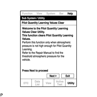
Press "Next".
-
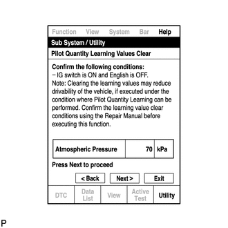
Confirm that the atmospheric pressure screen is displayed.
-
Confirm the displayed atmospheric pressure.
Standard Atmosphere Pressure is below 87 kPa Note
-
If the atmospheric pressure is higher than the standard range for performing "Pilot Quantity Learning Value Clear", do not clear the learned values. Instead, perform "Pilot Quantity Learning".
-
When the atmospheric pressure is higher than the standard range, perform "Pilot Quantity Learning" without initializing the learned values using "Pilot Quantity Learning Value Clear". If the learned values are initialized when the atmospheric pressure is higher than the standard range, the following symptoms may appear. Be sure to correctly follow procedures.
-
Driveability problems
-
Rough idle
-
Emission of white or black smoke, etc.
-
-
Proceed to the next screen.
-
-
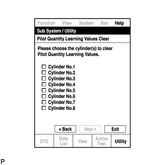
Select the cylinders whose learned value will be cleared.
Note
-
Multiple cylinders can be selected.
-
Only the cylinders for which injector compensation codes have been written must have their learned value cleared.
-
-
After selecting the cylinders whose learned value will be cleared, press "Next" to begin the initialization.
-
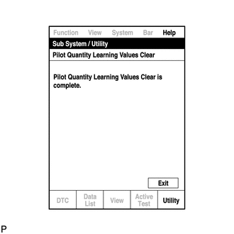
When the screen changes, push "Exit".
-
Turn the GTS off and turn the engine switch off.
-
Wait for at least 10 seconds.
-
Turn the engine switch on (IG) and turn the GTS on.
-
Clear the DTCs.
-
Turn the engine switch off and leave the vehicle for 30 seconds or more.
-
Turn the engine switch on (IG) for 1 second.
-
Enter the following menus: Engine and ECT / Trouble Codes.
-
Read the DTCs.
-
Confirm that no DTCs are output.
-
-
DESCRIPTION OF VIN
Note
The Vehicle Identification Number (VIN) must be input into the replacement ECM.
Tech Tips
The VIN is a 17-digit alphanumeric value. An GTS is required to register the VIN.
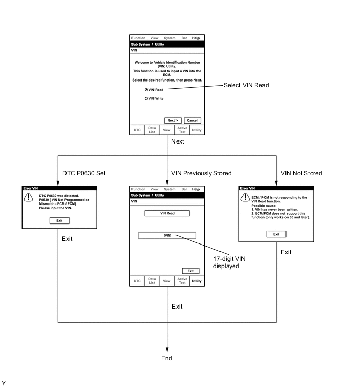
This registration section consists of two parts, Read VIN and Write VIN.
-
Read VIN: Explains the VIN reading process in a flowchart. This process allows the VIN stored in the ECM to be read, in order to confirm that the two VINs, the VIN provided with the vehicle and the VIN stored in the vehicle's ECM, are the same.
-
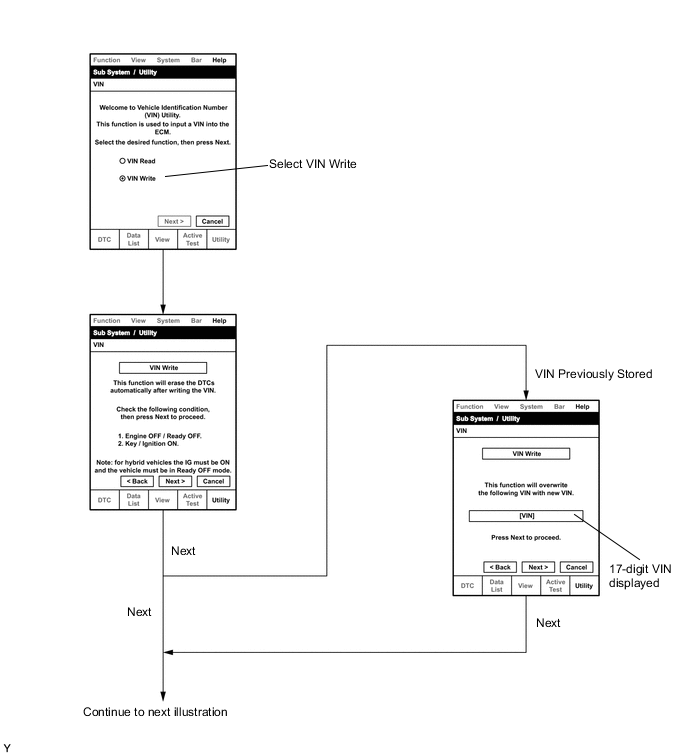
Write VIN: Explains the VIN writing process in a flowchart. This process allows the VIN to be input into the ECM. If the ECM is changed, or the ECM VIN and vehicle VIN do not match, the VIN can be registered, or overwritten in the ECM by following this procedure.
-
-
READ VIN
-
Confirm the vehicle VIN.
-
Connect the GTS to the DLC3.
-
Turn the engine switch on (IG).
-
Turn the GTS on.
-
Select the following menu items: Engine and ECT / Utility / VIN.
-
-
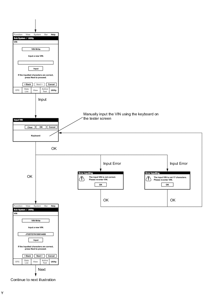
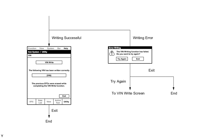
WRITE VIN
-
Confirm the vehicle VIN.
-
Connect the GTS to the DLC3.
-
Turn the engine switch on (IG).
-
Turn the GTS on.
-
Select the following menu items: Engine and ECT / Utility / VIN.
-
-
-
INITIALIZATION RELATED TO ECD SYSTEM (w/ DPF)
-
INITIALIZATION PROCEDURE FOR DIESEL THROTTLE BODY ASSEMBLY, EGR VALVE ASSEMBLY AND TURBOCHARGER SUB-ASSEMBLY
Tech Tips
When the diesel throttle body assembly, EGR valve assembly or turbocharger sub-assembly is replaced, perform initialization
-
Turn the engine switch on (IG).
Note
Do not start the engine.
-
Turn the engine switch off and wait for 30 seconds or more.
-
Turn the engine switch on (IG) and wait for 10 seconds or more.
-
-
CATALYST RECORD OF DPF THERMAL DETERIORATION CLEAR FUNCTION
Tech Tips
When the front exhaust pipe assemblies (DPF catalytic converter) or monolithic converter assemblies (CCo catalytic converter) are replaced, the catalyst record of thermal deterioration stored in the ECM must be cleared.
-
Connect the GTS to the DLC3.
-
Turn the engine switch on (IG).
-
Turn the GTS on.
-
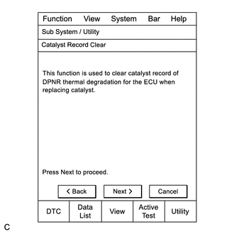
Enter the menu options in this order: Engine and ECT / Utility / Catalyst Record Clear.
-
Press "Next".
-
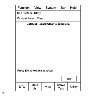
Press "Exit".
-
-
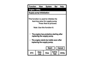
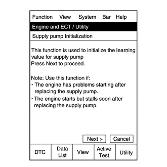
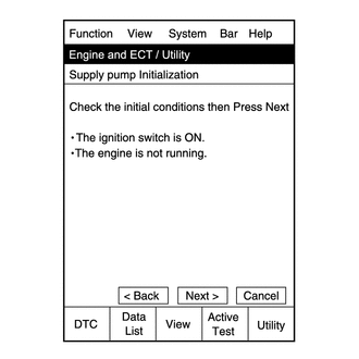
SUPPLY PUMP INITIALIZATION PROCEDURE
Tech Tips
After replacing the fuel supply pump assembly and/or ECM:
-
If the engine is defective or stalls immediately after startup, the learned values of the ECM must be initialized. The engine can be initialized through the GTS or by connecting DLC3 terminals.
-
If the engine starts normally, initialization is not necessary. Perform the steps labeled procedure "A" and procedure "B" only.
-
Connect the GTS to the DLC3.
-
Turn the engine switch on (IG).
Note
Do not start the engine.
-
Turn the GTS on.
-
Enter the following menus: Engine and ECT / Utility / Supply Pump Initialization.
-
Press "Next".
-
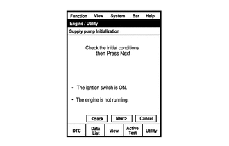
Press "Next".
-
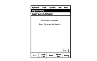
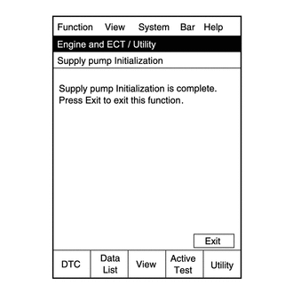
Press "Exit".
-
Start the engine to check if the initialization is complete. If the engine cannot be started, repeat the initialization procedures from the beginning (Procedure "A").
-
Idle the engine for at least 1 minute under the following conditions: (Procedure "B")
-
The engine coolant temperature is 60°C (140°F) or higher.
-
The fuel temperature is 20°C (68°F) or higher.
Note
Do not race the engine immediately after starting the engine. After warming up the engine, racing the engine is acceptable.
Tech Tips
-
The engine coolant temperature can be estimated by touching the outlet hose.
-
The fuel temperature can be estimated by using the ambient temperature as a substitute.
-
If the engine coolant temperature is difficult to estimate, use the GTS and enter the following menus: Engine and ECT / Data List / Coolant Temp.
-
-
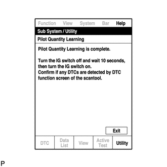
Initialization is complete.
-
-
CRANK TIME COMPENSATION RESET FUNCTION
-
This procedure uses the GTS to perform "Crank Time Compensation Reset".
-
When replacing the timing rotor (engine assembly), perform "Crank Time Compensation Reset".
Tech Tips
-
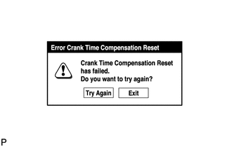
If an error occurs during compensation reset, check the vehicle condition, and then perform compensation reset again.
-
A communication malfunction may occur if there is a problem with the ECM, a wire harness or the connection to the DLC3. If the wire harnesses and the connection to the DLC3 are inspected and found to be normal, the ECM may be malfunctioning.
-
Connect the GTS to the DLC3.
-
Turn the engine switch on (IG).
Note
Do not start the engine.
-
Turn the GTS on.
-
Enter the following menus: Engine and ECT / Utility / Crank Time Compensation Reset.
-
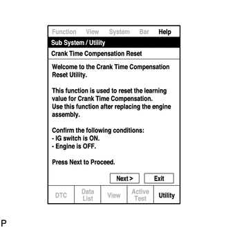
When the first screen is displayed, check the vehicle condition and push "Next".
-
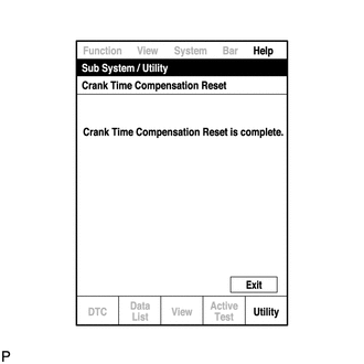
When the screen indicating reset completion is displayed, push "Exit".
-
-
A/F SENSOR COMPENSATION RESET FUNCTION
-
This procedure uses the GTS to perform "A/F Sensor Compensation Reset".
-
When replacing the A/F sensor, replace the sensor and then perform "A/F Sensor Compensation Reset".
Tech Tips
-

If an error occurs during compensation reset, check the vehicle condition, and then perform compensation reset again.
-
A communication malfunction may occur if there is a problem with the ECM, a wire harness or the connection to the DLC3. If the wire harnesses and the connection to the DLC3 are inspected and found to be normal, the ECM may be malfunctioning.
-
Connect the GTS to the DLC3.
-
Turn the engine switch on (IG).
Note
Do not start the engine.
-
Turn the GTS on.
-
Enter the following menus: Engine and ECT / Utility / A/F Sensor Compensation Reset.
-

When the first screen is displayed, check the vehicle condition and push "Next".
-

When the screen indicating reset completion is displayed, push "Exit".
-
-
-
REGISTRATION RELATED TO ECD SYSTEM (w/o DPF)
-
Example *1 Injector Compensation Code REGISTRATION
Note
-
When a fuel injector is replaced, the new fuel injector compensation code must be input into the ECM. When the ECM is replaced, all of the existing fuel injector compensation codes must be input into the new ECM.
-
Fuel injector compensation codes are unique, 30 digit, alphanumeric values printed on the head portion of each fuel injector. If an incorrect fuel injector compensation code is input into the ECM, the engine assembly may rattle or engine idling may become rough. In addition, engine failure may occur and the life of the engine may be shortened.
-
After replacing fuel injector(s) with new one(s), input compensation code(s) of fuel injector(s) into ECM as follows:
Tech Tips
-
Each fuel injector has different fuel injection characteristics. In order to optimize the fuel injections, the ECM uses the compensation codes to balance the different fuel injections between each fuel injector.
-
When you first turn the ignition switch to ON after replacing the ECM or a fuel injector(s), DTC P1601 is set. This is to inform you that registration of a fuel injector compensation code(s) is/are required. Manually clear the DTC upon completion of the compensation code registration.
-
Input the compensation code(s), which is/are imprinted on the head portion(s) of the new fuel injector(s), into the intelligent tester.
-
Input the new compensation code(s) into the ECM using the tester.
-
Turn the tester off and turn the ignition switch off.
-
Wait for at least 30 seconds.
-
Turn the ignition switch to ON and turn the tester on.
-
Clear DTC P1601 stored in the ECM using the tester.
-
-
Register compensation code.
-
Connect the intelligent tester to the DLC3.
-
Turn the ignition switch to ON .
Note
Do not start the engine.
-
Turn the tester on.
-
Enter the following menus: Powertrain / Engine / Utility / Injector Compensation.
-
Press Next.
-
Press Next again to proceed.
-
Select "Set Compensation Code".
-
Press Next.
-
Select the number of the cylinder corresponding to the fuel injector compensation code that you want to read.
-
Press Next.
-
Register compensation code.
-
Press Input.
-
Manually input the cylinder compensation code using the keyboard on the tester screen. The code is a 30 digit, alphanumeric value printed on the injector head portion.
Tech Tips
Each fuel injector compensation code is unique. The compensation code for each selected cylinder must be input into the tester correctly.
-
Confirm that the compensation code for the selected cylinder is correct, and then press OK.
-
Check that the compensation code displayed on the screen is correct by comparing it with the 30 digit alphanumeric value on the head portion of the fuel injector.
Note
If an incorrect fuel injector compensation code is input into the ECM, the engine may rattle or engine idling may become rough. In addition, engine failure may occur and the life of the engine may be shortened.
Tech Tips
-
If a wrong compensation code is input or read, return to the Input Value screen by pressing Input.
-
The saving process may fail due to a problem with the wire harness or a bad connection with the DLC3. Check the wire harness and DLC3 connection. If no problem is found with either, the ECM may be malfunctioning. Check the ECM and repeat this operation.
-
-
Press Next to register the compensation code in the ECM.
Tech Tips
-
If the registration process fails, the compensation code may be incorrect. Check the compensation code again.
-
If the input compensation code fails to register even though it is input correctly, there may be a problem with the wire harness or a bad connection with the DLC3. Check the wire harness and DLC3 connection. If no problem is found with either, the ECM may be malfunctioning. Check the ECM and restart this operation.
-
-
If you want to continue with other compensation code registrations, press Next. To finish the registration, press Cancel.
-
Turn the ignition switch off and then turn the tester off.
-
Wait for at least 30 seconds.
-
Turn the ignition switch to ON and then turn the tester on.
-
Clear DTC P1601 stored in the ECM using the tester.
-
-
-
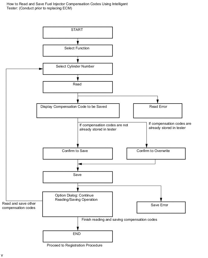
READING REGISTERED DATA
Note
-
When a fuel injector is replaced, the new fuel injector compensation code must be input into the ECM. When the ECM is changed, all of the existing fuel injector compensation codes must be input into the new ECM.
-
Fuel injector compensation codes are unique, 30 digit, alphanumeric values printed on the head portion of each fuel injector. If an incorrect fuel injector compensation code is input into the ECM, the engine may rattle or engine idling may become rough. In addition, engine failure may occur and the life of the engine may be shortened.
-
When replacing ECM with a new one, input all fuel injector compensation codes into new ECM as follows:
Tech Tips
-
Each fuel injector has different fuel injection characteristics. In order to optimize the fuel injections, the ECM uses the compensation codes to balance the different fuel injections between each injector.
-
When you first turn the ignition switch to ON after replacing the ECM or a fuel injector(s), DTC P1601 is set. This is to inform you that registration of a fuel injector compensation codes(s) is/are required. Manually clear the DTC upon completion of the compensation code registration.
-
Prior to replacing the ECM, read and save each fuel injector compensation code, stored in the original ECM, using the intelligent tester.
-
After installing a new ECM, input the saved compensation codes into the new ECM using the tester.
-
Turn the tester off and turn the ignition switch off.
-
Wait for at least 30 seconds.
-
Turn the ignition switch to ON and turn the tester on.
-
Clear DTC P1601 stored in the ECM using the tester.
-
-
Read and save fuel injector compensation codes.
Tech Tips
The following operation is available with ECMs that can transmit the registered fuel injector compensation codes to the intelligent tester.
-
Example *1 Injector Compensation Code Connect the intelligent tester to the DLC3.
-
Turn the ignition switch to ON.
Note
Do not start the engine.
-
Turn the tester on.
-
Enter the following menus: Powertrain / Engine / Utility / Injector Compensation.
-
Press Next.
-
Press Next again to proceed.
-
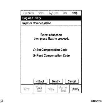
Select Read Compensation Code.
-
Press Next.
-
Select the number of the cylinder corresponding to the fuel injector compensation code that you want to read.
-
Press Next.
Tech Tips
The reading process may fail due to a problem with the wire harness or a bad connection with the DLC3. Check the wire harness and DLC3 connection. If no problem is found, the ECM may be malfunctioning. Check the ECM and restart this operation.
-
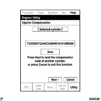
Check the fuel injector compensation code (30 digit alphanumeric value) displayed on the tester screen.
-
Press Save.
-
Check that the compensation code displayed on the tester screen is correct.
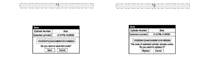
*1 When no fuel injector compensation code for the cylinder exists in the tester: *2 When another fuel injector compensation code for the cylinder exists in the tester: -
Press Save or Replace to save the fuel injector compensation code.
Tech Tips
-
The existing compensation code is overwritten with the new compensation code and is deleted from the tester.
-
The saving process may fail due to a problem with the wire harness or a bad connection with the DLC3. Check the wire harness and DLC3 connection. If no problem is found with either, the ECM may be malfunctioning. Check the ECM and restart this operation.
-
-
If you want to read and save other fuel injector compensation codes for other cylinders, press Next to continue. To finish this operation, press Cancel.
-
Turn the ignition switch off.
-
Turn the tester off.
-
Replace the ECM.
-
Example *1 Injector Compensation Code Connect the intelligent tester to the DLC3.
-
Turn the ignition switch to ON.
Note
Do not start the engine.
-
Turn the tester on.
-
Enter the following menus: Powertrain / Engine / Utility / Injector Compensation.
-
Press Next.
-
Press Next again to proceed.
-
Select Set Compensation Code.
-
Press Next.
-
Select the number of the cylinder corresponding to the fuel injector compensation code that you want to read.
-
Press Next.
-
Check that the compensation code displayed on the screen is correct by comparing it with the 30 digit alphanumeric value on the head portion of the fuel injector.
Note
If an incorrect fuel injector compensation code is input into the ECM, the engine may rattle or engine idling may become rough. In addition, engine failure may occur and the life of the engine may be shortened.
Tech Tips
-
If a wrong compensation code is input or read, return to the Input Value screen by pressing input.
-
The saving process may fail due to a problem with the wire harness or a bad connection with the DLC3. Check the wire harness and DLC3 connection. If no problem is found with either, the ECM may be malfunctioning. Check the ECM and repeat this operation.
-
-
Press Next to register the compensation code in the ECM.
Tech Tips
-
If the registration process fails, the compensation code may be incorrect. Check the compensation code again.
-
If the input compensation code fails to register even though it is input correctly, there may be a problem with the wire harness or a bad connection with the DLC3. Check the wire harness and DLC3 connection. If no problem is found with either, the ECM may be malfunctioning. Check the ECM and restart this operation.
-
-
If you want to continue with other compensation code registrations, press Next. To finish the registration, press Cancel.
-
Turn the ignition switch off and then turn the tester off.
-
Wait for at least 30 seconds.
-
Turn the ignition switch to ON and then turn the tester on.
-
Clear DTC P1601 stored in the ECM using the tester.
-
-
-
-
INITIALIZATION RELATED TO ECD SYSTEM (w/o DPF)
-
FUEL SUPPLY PUMP INITIALIZATION PROCEDURE
Tech Tips
After replacing the supply pump and/or the ECM, the ECM learned values must be initialized.
The engine can be initialized through the intelligent tester or by connecting DLC3 terminals.
-
Connect the intelligent tester to the DLC3.
-
Turn the ignition switch to ON.
Note
Do not start the engine.
-
Turn the tester on.
-
Enter the following menus: Powertrain / Engine / Utility / Supply Pump Initialization.
-
Press "Next".
-
Press "Next".
-
Press "Exit".
-
Start the engine to check if the initialization is complete. If the engine cannot be started, repeat the initialization procedures from the beginning.
-
Idle the engine for at least 1 minute under the following conditions:
-
The engine coolant temperature is 60°C (140°F) or more.
-
The fuel temperature is 20°C (68°F) or more.
Note
Do not race the engine immediately after starting the engine. After warming up the engine, racing the engine is acceptable.
Tech Tips
If the engine coolant temperature is difficult to estimate, use the intelligent tester and enter the following menus: Powertrain / Engine / Data List / Coolant Temp and Fuel Temperature.
-
-
Initialization is complete.
-
-
-
INITIALIZATION RELATED TO DYNAMIC RADAR CRUISE CONTROL
Note
After removing and installing or replacing the distance control ECU, be sure to perform the following procedures.
-
Turn the engine switch on (IG).
-
Turn the cruise control main switch on.
-
Depress the brake pedal (brake switch on).
-
With the brake pedal depressed, push the cruise control main switch to +RES 3 times within 3 seconds, and check that the buzzer sounds.
Note
At this time, do not turn the headlight dimmer switch on. Due to the activation of the beam axis automatic adjustment mode, turning the headlight dimmer switch on may result in an incorrect setting. If the headlight dimmer switch is turned on by mistake, perform the beam axis adjustment again.
-
-
ADJUSTMENT FOR MILLIMETER WAVE RADAR SENSOR
-
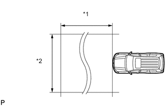
Text in Illustration *1 Approx. 10 m *2 Approx. 14 m ADJUST MILLIMETER WAVE RADAR SENSOR ASSEMBLY
Note
-
Perform measurements on a level surface.
-
Make sure that there are no metal objects on the ground or within a 10 m (32.8 ft.) x 14 m (45.9 ft.) area in front of the vehicle. If possible, the surrounding area should also be free of large metal objects.
-
Before adjusting, perform the following:
-
Remove all cargo from the inside of the vehicle.
-
Adjust the tire pressure to the specified value(s).
-
-
w/ Air suspension:
Adjust the vehicle's height to the standard height.
-
Adjust the vertical direction.
-
Remove any dust and oil from the level rack of the millimeter wave radar sensor assembly.
-
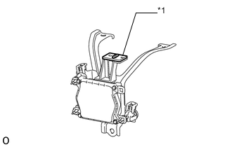
Text in Illustration *1 Level Set a level for use with the sensor in the center of the level rack of the millimeter wave radar sensor assembly.
-
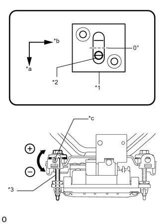
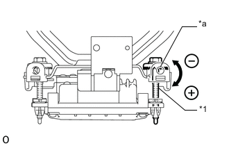
Text in Illustration *1 Level *2 Air Bubble *3 Bolt A *a FR *b LH *c Screwdriver Insertion Hole Using a screwdriver, adjust the sensor by turning the vertical adjusting bolt of the millimeter wave radar sensor assembly (bolt A) until the air bubble is centered on the red line of the level as shown in the illustration.
Standard 0.2° upward Tech Tips
The adjustable range within the red frame of the level is +/-0.2°.
Adjustment: Vertical adjustment
-
Upward direction: Turn bolt A in minus direction
-
Downward direction: Turn bolt A in plus direction
For 1 complete turn of screwdriver, sensor moves about 0.12° -
-
-
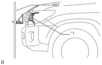
Text in Illustration *1 Millimeter Wave Radar Sensor Adjust SST (reflector) height.
- SST
- 09870-60000 ( 09870-60010 )
- 09870-60040
-
Adjust SST (reflector) so that the center of SST (reflector) is the same height as the millimeter wave radar sensor assembly.
-
Place SST (reflector).
-
Hang a pointed weight from the center of the front and rear bumpers of the vehicle (center of the emblem) and accurately mark the center points on the ground.
-
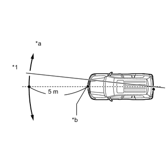
Text in Illustration *1 String *a Adjust Center By Moving String To Right And Left *b Extend String Through Front Center Mark Mark a point 5 m (16.4 ft.) in front of the vehicle on the line that connects the front and rear center point marks.
Tech Tips
Affix one end of a string to the rear center point mark and extend the string 5 m (16.4 ft.) from the front of the vehicle. Move the other end of the string left and right to align the string with the front center point mark and make a straight line.
-
Place SST at a position 12 mm (0.472 in.) from the marked position, to the right of the vehicle.
Note
Perform the operation as precisely as possible.
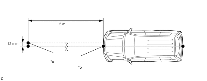
Text in Illustration *a Reflector (SST) Placement Point *b Millimeter Wave Radar Sensor Position
-
-
Adjust the beam axis.
-
Connect the intelligent tester to the DLC3.
-
Turn the engine switch on (IG).
-
Turn the intelligent tester main switch ON, and turn the cruise control main switch ON.
-
Select "Radar Cruise" from the display screen.
Tech Tips
A buzzer will sound for 1 second.
-
Select "Utility" from the display screen.
-
Select "Beam Axis Adjustment" from the display screen.
-
Follow the tester display, and continue with the adjustment.
-
Intelligent tester
Note
-
Turn the cruise control main switch ON before pressing Next.
-
Make sure there is at least 20 cm (7.9 inches) between the radar sensor and any nearby individuals.
-
-
Check the following items on the laser cruise divergence data screen.
CAUTION:
While using the intelligent tester's beam axis adjustment mode, the actual direction and angle of the radar sensor may be different from the intelligent tester's data. In such a case, the deviation is displayed on the combination meter's multi-information display.
-
-
Confirm that the distance value is approximately 5 m (16.41 ft.).
Tech Tips
-
A value between 0.0 and 6.3 m (20.67 ft.) is indicated.
-
If the distance is 0 m (0 ft.), the sensor cannot detect the target. Reconfirm that there is no metal in the specified area in front of the vehicle (refer to the NOTICE at the beginning of this adjustment procedure).
-
-
Confirm that the left/right side value is between 0.0 and 6.3.
Tech Tips
If the distance is 0 m (0 ft.), the sensor cannot detect the target. Reconfirm that there is no metal in the specified area in front of the vehicle (refer to the NOTICE at the beginning of this adjustment procedure).
-
-
-
Adjust the horizontal direction.
-
Read the current amount of angle deviation.
Standard 0° (Both left and right) -
Text in Illustration *1 Bolt B *a Screwdriver Insertion Hole Based on the results of the beam axis deviation measurement, using a screwdriver, adjust the sensor by turning the horizontal adjusting bolt of the millimeter wave radar sensor assembly (bolt B).
Adjustment: Horizontal adjustment Right direction: Turn bolt B in plus direction
Left direction: Turn bolt B in minus direction
For 1 complete turn of screwdriver, sensor moves about 0.07° Note
If it is difficult to reach a value of 0°, it is possible that the sensor is targeting an object other than SST. Reconfirm that there are no reflective objects in the surrounding area.
-
Text in Illustration *1 Aluminum foil Because the driving learned value will be reset, cover the left half of the sensor with aluminum foil or equivalent (a metal material that blocks electric waves) for a period of approximately 10 seconds.
Note
At this time, leave SST in place and make sure there are no objects between the right half of the sensor and the reflector.
Tech Tips
When the value is reset, the buzzer will sound for 10 seconds, a distance value between 0 and 6.3° and a right side value between 0 and 6.3 m (20.7 ft.) will be displayed on the screen.
-
Continue the procedure according to the display to complete the beam axis adjustment.
-
Disconnect the intelligent tester from the vehicle.
-
-
Reconfirm the vertical direction.
-
Text in Illustration *1 Level Set a level for use with the sensor in the center of the level rack of the millimeter wave radar sensor assembly.
-
Text in Illustration *1 Level *2 Air Bubble *3 Bolt A *a FR *b LH *c Screwdriver Insertion Hole Using a screwdriver, adjust the sensor by turning the vertical adjusting bolt of the millimeter wave radar sensor assembly (bolt A) until the air bubble is centered on the red line of the level as shown in the illustration.
Standard 0.2° upward Tech Tips
The adjustable range within the red frame of the level is +/-0.2°.
Adjustment: Vertical adjustment
-
Upward direction: Turn bolt A in minus direction
-
Downward direction: Turn bolt A in plus direction
For 1 complete turn of screwdriver, sensor moves about 0.12° -
-
-
-
DRIVE TEST
-
Perform the drive test.
Note
-
Be sure to perform the driving test after adjusting the millimeter wave radar sensor assembly.
-
Be careful when driving.
-
Drive at 30 km/h (19 mph) on a straight road with good visibility while staying in the center of the lane.
Note
Because the pre-crash safety system may activate under the following conditions, avoid conditions like these when performing the test.
-
There are objects on the side of the road at the beginning of a curve.
-
Passing an oncoming vehicle on a curve.
-
Crossing a narrow metal bridge.
-
There are metal objects on the road surface.
-
There is an oncoming vehicle when turning right.
-
Rapidly approaching a vehicle driving in front.
-
-
On a straight road, when passing an oncoming vehicle with no danger of collision, check that the master warning does not illuminate and that the buzzer does not sound. At the same time, check that "BRAKE!" is not displayed on the display in the combination meter.
-
If "BRAKE!" is displayed, perform the millimeter wave radar sensor assembly adjustment again.
Tech Tips
-
Check the installation condition of the millimeter wave radar sensor assembly.
-
Check that the pre-crash safety brake switch is not pushed in.
-
-
-
-
-
INITIALIZATION RELATED TO AUTOMATIC TRANSMISSION SYSTEM (for A750F, 1GR-FE)
-
RESET MEMORY
Note
-
Perform the Reset Memory (AT initialization) when replacing the automatic transmission assembly, valve body assembly or any of the shift solenoid valves.
-
The Reset Memory can be performed only with the intelligent tester.
Tech Tips
The ECM memorizes the control conditions of the automatic transmission assembly and engine assembly. Therefore, when the automatic transmission assembly, valve body assembly or any of the shift solenoid valves has been replaced, it is necessary to reset the memory so that the ECM can memorize the new information.
-
Connect the intelligent tester to the DLC3.
-
Turn the engine switch on (IG).
-
Turn the intelligent tester on.
-
Enter the following menus: Powertrain / Engine and ECT / Utility / Reset Memory.
Note
After performing the Reset Memory, be sure to perform the Road Test described earlier.
Tech Tips
The ECM learns through the road test.
-
-
-
INITIALIZATION RELATED TO AUTOMATIC TRANSMISSION SYSTEM (for AB60F, 1UR-FE)
-
RESET MEMORY
Note
-
Perform Reset Memory (AT initialization) when replacing the automatic transmission assembly, valve body assembly or any of the shift solenoid valves.
-
Reset Memory can be performed only with the GTS.
Tech Tips
The ECM memorizes the control conditions of the automatic transmission assembly and engine assembly. Therefore, when the automatic transmission assembly, valve body assembly or any of the shift solenoid valves has been replaced, it is necessary to reset the memory so that the ECM can memorize the new information.
The reset procedure is as follows.
-
Connect the GTS to the DLC3.
-
Turn the engine switch on (IG).
-
Turn the GTS on.
-
Enter the following menus: Powertrain / Engine and ECT / Utility / Reset Memory.
Note
After performing Reset Memory, be sure to perform the Road Test described earlier.
Tech Tips
The ECM learns through the Road Test.
-
-
-
INITIALIZATION RELATED TO AUTOMATIC TRANSMISSION SYSTEM (for AB60F, 3UR-FE)
-
RESET MEMORY
Note
-
Perform Reset Memory (AT initialization) when replacing the automatic transmission assembly, valve body assembly or any of the shift solenoid valves.
-
Reset Memory can be performed only with the GTS.
Tech Tips
The ECM memorizes the control conditions of the automatic transmission assembly and engine assembly. Therefore, when the automatic transmission assembly, valve body assembly or any of the shift solenoid valves has been replaced, it is necessary to reset the memory so that the ECM can memorize the new information.
The reset procedure is as follows.
-
Connect the GTS to the DLC3.
-
Turn the engine switch on (IG).
-
Turn the GTS on.
-
Enter the following menus: Powertrain / Engine and ECT / Utility / Reset Memory.
Note
After performing Reset Memory, be sure to perform the Road Test described earlier.
Tech Tips
The ECM learns through the Road Test.
-
-
-
INITIALIZATION RELATED TO AUTOMATIC TRANSMISSION SYSTEM (for 1VD-FTV, AB60F)
-
RESET MEMORY
Note
-
Perform the Reset Memory (AT initialization) when replacing the automatic transmission assembly, valve body assembly or any of the shift solenoid valves.
-
The Reset Memory can be performed only with the intelligent tester.
Tech Tips
The ECM memorizes the control conditions of the automatic transmission assembly and engine assembly. Therefore, when the automatic transmission assembly, valve body assembly or any of the shift solenoid valves has been replaced, it is necessary to reset the memory so that the ECM can memorize the new information.
-
Connect the intelligent tester to the DLC3.
-
Turn the ignition switch to ON.
-
Turn the intelligent tester on.
-
Enter the following menus: Powertrain / ECT / Utility / Reset Memory.
Note
After performing the Reset Memory, be sure to perform the Road Test described earlier.
Tech Tips
The ECM learns through the Road Test.
-
-
-
INITIALIZATION RELATED TO AUTOMATIC TRANSMISSION SYSTEM (for 1VD-FTV with DPF, AB60F)
-
RESET MEMORY
Note
-
Perform the Reset Memory (AT initialization) when replacing the automatic transmission assembly, valve body assembly or any of the shift solenoid valves.
-
The Reset Memory can be performed only with the GTS.
Tech Tips
The ECM memorizes the control conditions of the automatic transmission assembly and engine assembly. Therefore, when the automatic transmission assembly, valve body assembly or any of the shift solenoid valves has been replaced, it is necessary to reset the memory so that the ECM can memorize the new information.
-
Connect the GTS to the DLC3.
-
Turn the engine switch on (IG).
-
Turn the GTS on.
-
Enter the following menus: Powertrain / Engine and ECT / Utility / Reset Memory.
Note
After performing the Reset Memory, be sure to perform the Road Test described earlier.
Tech Tips
The ECM learns through the Road Test.
-
-
-
ADJUSTMENT FOR AUTOMATIC TRANSMISSION FLUID (A750F)
-
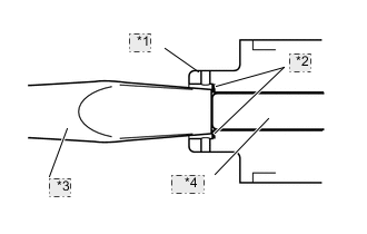
*1 Refill Hole *2 Refill Plug *3 Overflow Plug BEFORE FILLING TRANSMISSION
-
This transmission requires Toyota Genuine ATF WS transmission fluid.
-
After servicing the transmission, you must refill the transmission with the correct amount of fluid.
-
Keep the vehicle level while adjusting the fluid level.
-
Proceed to the "Transmission Pan Fill" procedures if you replaced the entire transmission, transmission pan, drain plug, valve body and/or torque converter.
-
Proceed to the ''Transmission Fill'' procedures after removing the refill plug if you replaced the transmission hose and/or output shaft oil seal.
-
-
*1 Overflow Tube *2 Specified Fluid Level TRANSMISSION PAN FILL
-
Remove the refill plug and overflow plug.
-
Fill the transmission through the refill hole until fluid begins to trickle out of the overflow tube.
-
Reinstall the overflow plug.
-
-
TRANSMISSION FILL
-
w/o Air Cooled Transmission Oil Cooler (w/ ATF Warmer):
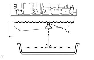
Push the shaft of the thermostat and fix it in place.
-
By using compressed air, etc., blow dust off of the thermostat cap to clean it.
-
*1 Cap *2 Step *3 Screwdriver *4 Shaft Using a screwdriver, push the shaft of the thermostat.
Tech Tips
-
Pushed amount: 5.5 to 7.0 mm (0.217 to 0.276 in.)
-
Push the shaft until the screwdriver contacts the inside step of the cap.
-
-
With the shaft of the thermostat pressed, push a pin (diameter: 1.0 to 1.8 mm (0.0394 to 0.0709 in.)) into a hole on the side of the thermostat cap. Insert the pin until it passes through the hole on the other side of the thermostat cap to fix the shaft in place.
-
-
Fill the transmission with the amount of fluid listed in the table below.
-
Reinstall the refill plug to prevent the fluid from splashing.
Tech Tips
If you cannot add the listed amount of fluid, do the following:
-
Install the refill plug.
-
Allow the engine to idle with the air conditioning off.
-
Move the shift lever through the entire gear range to circulate fluid.
-
Wait for 30 seconds with the engine idling.
-
Stop the engine.
-
Remove the refill plug and add fluid.
-
Reinstall the refill plug.
-
-
-
ADJUST FLUID TEMPERATURE
Note
The fluid temperature can be confirmed by checking the indicator light in the meter or by using the GTS. When using the GTS, it is necessary to change to temperature detection mode in order to idle the vehicle appropriately.
-
When using the GTS:
-
Turn the engine switch off.
-
Connect the GTS to the DLC3.
-
Turn the engine switch on (IG).
-
Enter the following menus: Powertrain / Engine and ECT / Active Test / Connect the TC and TE1.
-
Enter the following menus: Powertrain / ECT / Data List / A/T Oil Temperature 1.
-
Check the ATF temperature.
Note
-
The ATF temperature must be between 38 to 45°C (100 to 113°F).
-
If the ATF temperature is not between 38 to 45°C (100 to 113°F), turn the ignition switch off and wait until the fluid temperature drops between 38 to 45°C (100 to 113°F).
-
-
According to the display on the GTS, perform the Active Test "Connect the TC and TE1".
Tech Tips
Indicator lights of the meter blink to output Trouble Codes when TC and TE1 are connected.
-
Start the engine.
Note
Check that electrical systems such as the air conditioning system, audio system and lighting system are off.
-
-
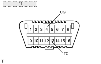
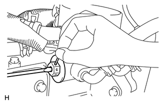
*1 Front view of DLC3: When not using the GTS:
- SST
- 09843-18040
-
Using SST, connect terminals 13 (TC) and 4 (CG) of the DLC3.
-
Start the engine.
Note
Check that electrical systems such as the air conditioning system, audio system and lighting system are off.
Tech Tips
Indicator lights of the meter blink to output Trouble Codes when terminals TC and CG are connected.
-
Slowly move the shift lever from P to S, then change the gears from 1st to 6th. Then return the shift lever to P.
Tech Tips
Slowly move the shift lever to circulate the fluid through each part of the transmission.
-
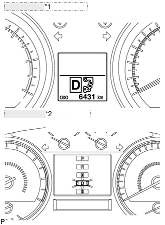
*1 w/ Multi-information Display: *2 w/o Multi-information Display: Move the shift lever to D, and quickly move back and forth between N and D (once within 1.5 seconds) for at least 6 seconds. This will activate the fluid temperature detection mode.
-
When using the GTS:
-
Return the shift lever to P and press OFF on the Active Test display.
-
-
When not using the GTS:
-
Return the shift lever to P and disconnect terminals 13 (TC) and 4 (CG).
-
-
Allow the engine to idle until the fluid temperature reaches 38 to 45°C (100 to 113°F).
-
The indicator (D) will come on again when the fluid temperature reaches 38°C (100°F) and will blink when it exceeds 46°C (113°F).
Note
Perform the fluid level inspection while the indicator light is on.
-
-
FLUID LEVEL CHECK
Note
The fluid temperature must be between 38 to 45°C (100 to 113°F) to accurately check the fluid level.
-
*1 Overflow Tube *2 Specified Fluid Level Remove the overflow plug with the engine idling.
-
Check that fluid comes out of the overflow tube.
If fluid does not come out, proceed to the "Transmission Refill" procedures.
If fluid comes out, wait until the overflow slows to a trickle and proceed to the "Complete" procedures.
-
-
TRANSMISSION REFILL
-
Remove the overflow plug.
-
Remove the refill plug.
-
Add ATF into the refill hole until ATF flows from the overflow tube.
-
Wait until the overflow slows to a trickle and proceed to the ''COMPLETE'' procedures.
-
-
COMPLETE
-
Install a new gasket and the overflow plug.
- Torque:
- 20 N*m { 204 kgf*cm, 15 ft.*lbf }
-
Stop the engine.
-
Install a new gasket and the refill plug.
- Torque:
- 39 N*m { 400 kgf*cm, 29 ft.*lbf }
-
*1 Cap *2 Shaft w/o Air Cooled Transmission Oil Cooler (w/ ATF Warmer):
-
Remove the pin.
Note
-
Make sure the shaft of the thermostat is protruding from the hole of the cap.
-
Check that there is no ATF leaking from the cap hole.
-
-
-
-
-
ADJUSTMENT FOR AUTOMATIC TRANSMISSION FLUID (AB60F)
Note
-
This transmission requires Toyota Genuine ATF WS.
-
After servicing the transmission, you must follow the ATF adjustment procedure.
-
Maintain the vehicle in a horizontal position while adjusting the fluid level.
-
PRELIMINARY PROCEDURES (w/ ATF Warmer)
-
Using compressed air or equivalent, blow dust off the thermostat cap to clean it.
-
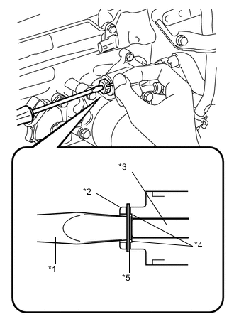
Text in Illustration *1 Screwdriver *2 Cap *3 Shaft *4 Step *5 Pin Using a screwdriver, push in the shaft of the thermostat.
Tech Tips
-
Pushed amount: 5.5 to 7.0 mm (0.217 to 0.276 in.)
-
Push in the shaft until the screwdriver contacts the step inside the cap.
-
-
With the shaft of the thermostat pressed, insert a pin into a hole on the side of the thermostat cap. Insert the pin until it passes through the hole on the other side of the thermostat cap to fix the shaft in place.
Tech Tips
Pin diameter: 1.0 to 1.8 mm (0.0394 to 0.0709 in.)
-
-
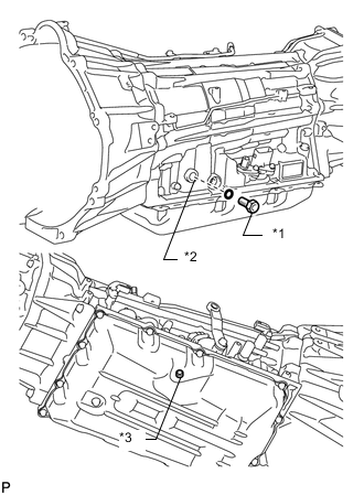
Text in Illustration *1 Refill Plug *2 Refill Hole *3 Overflow Plug BEFORE FILLING TRANSMISSION
-
This transmission requires Toyota Genuine ATF WS transmission fluid.
-
After servicing the transmission, you must refill the transmission with the correct amount of fluid.
-
Keep the vehicle level while adjusting the fluid level.
-
Proceed to the "Transmission Pan Fill" procedures if you replaced the entire transmission, transmission pan, drain plug, valve body and/or torque converter.
-
Proceed to the "Transmission Fill" procedures after removing the refill plug if you replaced the transmission hose and/or output shaft oil seal.
Text in Illustration *1 Refill Plug *2 Refill Hole *3 Overflow Plug
-
-
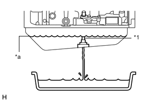
Text in Illustration *1 Overflow Tube *a Specified Fluid Level TRANSMISSION PAN FILL
-
Remove the refill plug and overflow plug.
-
Fill the transmission through the refill hole until fluid begins to trickle out of the overflow tube.
-
Reinstall the overflow plug.
-
-
TRANSMISSION FILL
-
Fill the transmission with the amount of fluid listed in the table below.
-
Reinstall the refill plug to prevent the fluid from splashing.
Tech Tips
If you cannot add the listed amount of fluid, do the following:
-
Install the refill plug.
-
Allow the engine to idle with the air conditioning OFF.
-
Move the shift lever through the entire gear range to circulate fluid.
-
Wait for 30 seconds with the engine idling.
-
Stop the engine.
-
Remove the refill plug and add fluid.
-
Reinstall the refill plug.
-
-
-
ADJUST FLUID TEMPERATURE
Note
The fluid temperature can be confirmed by checking the indicator light in the meter or by using the intelligent tester. When using the intelligent tester, it is necessary to change to temperature detection mode in order to idle the vehicle appropriately.
-
When using the intelligent tester:
-
Turn the ignition switch off.
-
Connect the intelligent tester to the DLC3.
-
Turn the ignition switch to ON.
-
Enter the following menus: Powertrain / Engine and ECT / Active Test / Connect the TC and TE1.
-
Enter the following menus: Powertrain / Engine and ECT / Data List / A/T Oil Temperature 1.
-
for 1VD-FTV:
Check the ATF temperature.
Note
-
The ATF temperature must be between 41 to 46°C (106 to 115°F).
-
If the ATF temperature is not between 41 to 46°C (106 to 115°F), turn the ignition switch off and wait until the fluid temperature drops between 41 to 46°C (106 to 115°F).
-
-
for 3UR-FE, 1UR-FE:
Check the ATF temperature.
Note
-
The ATF temperature must be between 43 to 48°C (109 to 118°F).
-
If the ATF temperature is not between 43 to 48°C (109 to 118°F), turn the ignition switch off and wait until the fluid temperature drops between 43 to 48°C (109 to 118°F).
-
-
for 1VD-FTV:
According to the display on the intelligent tester, perform the Active Test "Connect the TC and TE1".
-
for UR Engine Series:
According to the display on the intelligent tester, perform the Active Test "Connect the TC and TE1".
Tech Tips
Indicator lights of the combination meter blink to output DTCs when TC and TE1 are connected.
-
Start the engine.
Note
Check that electrical systems such as the air conditioning system, audio system and lighting system are off.
-
-
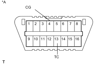
Text in Illustration *A Front View of DLC3 When not using the intelligent tester:
- SST
- 09843-18040
-
Using SST, connect terminals 13 (TC) and 4 (CG) of the DLC3.
-
Start the engine.
Note
Check that electrical systems such as the air conditioning system, audio system and lighting system are off.
Tech Tips
Indicator lights of the meter blink to output DTCs when terminals TC and CG are connected.
-
Slowly move the shift lever from P to S, then change the gears from 1st to 6th. Then return the shift lever to P.
Tech Tips
Slowly move the shift lever to circulate the fluid through each part of the transmission.
-
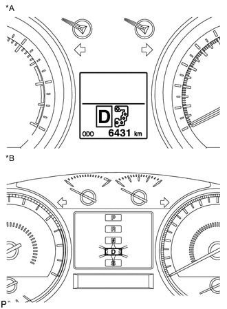
Text in Illustration *A w/ Multi-information Display *B w/o Multi-information Display Move the shift lever to D, and quickly move back and forth between N and D (once within 1.5 seconds) for at least 6 seconds. This will activate the fluid temperature detection mode.
-
When using the intelligent tester:
-
Return the shift lever to P and press OFF on the Active Test display.
-
-
When not using the intelligent tester:
-
Return the shift lever to P and disconnect terminals 13 (TC) and 4 (CG).
-
-
for 1VD-FTV:
Allow the engine to idle until the fluid temperature reaches 41 to 46°C (106 to 115°F).
-
for 3UR-FE, 1UR-FE:
Allow the engine to idle until the fluid temperature reaches 43 to 48°C (109 to 118°F).
-
for 1VD-FTV:
The indicator (D) will come on again when the fluid temperature reaches 41°C (106°F) and will blink when it exceeds 46°C (115°F).
Note
Perform the fluid level inspection while the indicator light is on.
-
for 3UR-FE, 1UR-FE:
The indicator (D) will come on again when the fluid temperature reaches 43°C (109°F) and will blink when it exceeds 48°C (118°F).
Note
Perform the fluid level inspection while the indicator light is on.
-
-
FLUID LEVEL CHECK
Note
-
for 1VD-FTV:
The fluid temperature must be between 41 and 46°C (106 and 115°F) to accurately check the fluid level.
-
for 3UR-FE, 1UR-FE:
The fluid temperature must be between 43 and 48°C (109 and 118°F) to accurately check the fluid level.
-
Text in Illustration *1 Overflow Tube *a Specified Fluid Level Remove the overflow plug with the engine idling.
-
Check that fluid comes out of the overflow tube.
If fluid does not come out, proceed to the "Transmission Refill" procedures.
If fluid comes out, wait until the overflow slows to a trickle and proceed to the "Complete" procedures.
-
-
TRANSMISSION REFILL
-
Remove the overflow plug.
-
Remove the refill plug and gasket.
-
Add ATF into the refill hole until ATF flows from the overflow tube.
-
Wait until the overflow slows to a trickle and proceed to the "Complete" procedures.
-
-
COMPLETE
-
Install a new gasket and the overflow plug.
- Torque:
- 20 N*m { 204 kgf*cm, 15 ft.*lbf }
-
Stop the engine.
-
Install a new gasket and the refill plug.
- Torque:
- 39 N*m { 400 kgf*cm, 29 ft.*lbf }
-
-
-
INITIALIZATION RELATED TO AUTOMATIC TRANSMISSION SYSTEM (for 3UR-FE, AB60F)
Note
If either of the following conditions is met, perform ATF Thermal Degradation Estimate Reset.
-
The ATF has been replaced.
-
Approximately 50% or more of the ATF has been replaced during a repair of the transmission or a similar operation.
-
Connect the GTS to the DLC3.
-
Turn the engine switch on (IG).
Note
Do not start the engine.
-
Turn the GTS on.
-
Enter the following menus: Powertrain / Engine and ECT / Utility / ATF Thermal Degradation Estimate Reset.
-
-
ADJUSTMENT FOR PARK/NEUTRAL POSITION SWITCH (for AUTOMATIC TRANSMISSION)
-
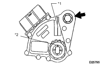
*1 Neutral Basic Line *2 Groove ADJUST PARK/NEUTRAL POSITION SWITCH ASSEMBLY
-
Loosen the bolt of the park/neutral position switch and move the shift lever to N.
-
Align the groove with the neutral basic line.
-
Hold the switch in the position described above and tighten the bolt.
- Torque:
- 13 N*m { 130 kgf*cm, 10 ft.*lbf }
-
After the adjustment, perform the on-vehicle inspection.
-
-
-
ADJUSTMENT FOR CLUTCH (for LHD)
-
INSPECT AND ADJUST CLUTCH PEDAL SUB-ASSEMBLY
-
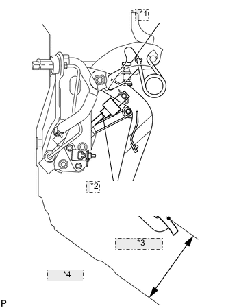
*1 Pedal Height Adjust Point *2 Push Rod Play and Pedal Free Play Adjust Point *3 Pedal Height *4 Tibia Pad Check that the clutch pedal height is correct.
-
Adjust the clutch pedal height.
-
Loosen the lock nut and turn the stopper bolt or clutch switch until the height is correct. Tighten the lock nut.
- Torque:
- 16 N*m { 160 kgf*cm, 12 ft.*lbf }
-
-
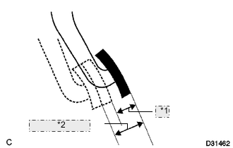
*1 Push Rod Play *2 Pedal Free Play Check that the clutch pedal free play and push rod play are correct.
-
Depress the clutch pedal until the clutch resistance begins to be felt.
Standard Pedal Free Play 5.0 to 15.0 mm (0.197 to 0.591 in.) -
Gently depress the clutch pedal until the resistance begins to increase a little.
Standard Push Rod Play at Pedal Top 1.0 to 5.0 mm (0.0394 to 0.197 in.)
-
-
Adjust the clutch pedal free play and push rod play.
-
Loosen the lock nut and turn the clutch push rod until the clutch pedal free play and push rod play are correct.
-
Tighten the lock nut.
-
After adjusting the clutch pedal free play and push rod play, check the clutch pedal height.
Standard Clutch Pedal Height from Tibia Pad 162.7 to 172.7 mm (6.41 to 6.79 in.)
- Torque:
- 12 N*m { 120 kgf*cm, 9 ft.*lbf }
-
-
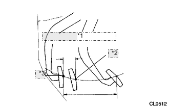
*1 20 mm (0.787 in.) or more *2 Release Point *3 Full Stroke End Position Check the clutch release point.
-
Pull the parking brake lever and chock the wheels.
-
Start the engine and allow it to idle.
-
Without depressing the clutch pedal, slowly move the shift lever to R until the gears engage.
-
Gradually depress the clutch pedal and measure the stroke distance from the point that the gear noise stops (release point) up to the full stroke end position.
Standard Distance from Pedal Stroke End Position to Release Point 20 mm (0.787 in.) or more If the distance is not as specified, perform the following operations:
-
-
Check the clutch pedal height.
-
Check the push rod play and pedal free play.
-
Bleed the clutch line.
-
Check the clutch cover and disc.
-
-
-
-
-
ADJUSTMENT FOR CLUTCH (for RHD)
-
INSPECT AND ADJUST CLUTCH PEDAL SUB-ASSEMBLY
-
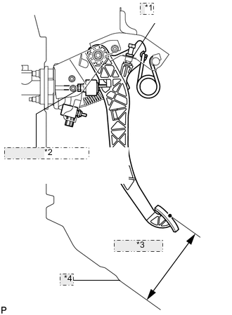
*1 Pedal Height Adjust Point *2 Push Rod Play and Pedal Free Play Adjust Point *3 Pedal Height *4 Tibia Pad Check that the clutch pedal height is correct.
-
Adjust the clutch pedal height.
-
Loosen the lock nut and turn the stopper bolt or clutch switch until the height is correct. Tighten the lock nut.
- Torque:
- 16 N*m { 160 kgf*cm, 12 ft.*lbf }
-
-
*1 Push Rod Play *2 Pedal Free Play Check that the clutch pedal free play and push rod play are correct.
-
Depress the clutch pedal until the clutch resistance begins to be felt.
Standard Clutch Pedal Free Play 5.0 to 15.0 mm (0.197 to 0.591 in.) -
Gently depress the clutch pedal until the resistance begins to increase a little.
Standard Push Rod Play at Pedal Top 1.0 to 5.0 mm (0.0394 to 0.197 in.)
-
-
Adjust the clutch pedal free play and push rod play.
-
Loosen the lock nut and turn the push rod until the clutch pedal free play and push rod play are correct.
-
Tighten the lock nut.
-
After adjusting the clutch pedal free play and push rod play, check the clutch pedal height.
Standard Clutch Pedal Height from Tibia Pad 164.8 to 174.8 mm (6.49 to 6.88 in.)
- Torque:
- 12 N*m { 120 kgf*cm, 9 ft.*lbf }
-
-
*1 20 mm (0.787 in.) or more *2 Release Point *3 Full Stroke End Position Check the clutch release point.
-
Pull the parking brake lever and chock the wheels.
-
Start the engine and allow it to idle.
-
Without depressing the clutch pedal, slowly move the shift lever to R until the gears engage.
-
Gradually depress the clutch pedal and measure the stroke distance from the point that the gear noise stops (release point) up to the full stroke end position.
Standard Distance from Pedal Stroke End Position to Release Point 20 mm (0.787 in.) or more If the distance is not as specified, perform the following operations:
-
-
Check the clutch pedal height.
-
Check the push rod play and pedal free play.
-
Bleed the clutch line.
-
Check the clutch cover and disc.
-
-
-
-
-
INITIALIZATION RELATED TO ACTIVE HEIGHT CONTROL SUSPENSION
-
DESCRIPTION
-
If replacing the suspension control ECU and/or height control sensor, perform the vehicle height offset calibration.
-
-
VEHICLE HEIGHT OFFSET CALIBRATION
Note
-
Make sure that the pressure of the tires is normal.
-
Make sure that the vehicle is empty.
-
Make sure that the parking brake is released and that the shift lever is in N.
-
-
PERFORM VEHICLE HEIGHT INSPECTION
-
Adjust the pressure of the tires.
-
Stabilize the suspension by releasing the parking brake and bouncing the corners of the vehicle up and down.
-
Start the engine.
-
Perform the following operation twice:
Set the vehicle height to LO with the height control switch, and then return the vehicle height to NORMAL.
-
Turn the engine switch off.
-
Connect the intelligent tester to the DLC3.
-
Move the shift lever to N and move the vehicle forward and rearward.
-
Turn the engine switch on (IG) and the tester on.
-
Check that the vehicle height is NORMAL.
Tech Tips
The N of the multi-information display height control indicator in the combination meter turns on.
-
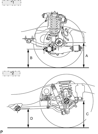
*1 Front Side: *2 Rear Side: Perform the vehicle height inspection.
-
Using a jack, set the vehicle to the standard vehicle height and eliminate any difference in height between the left and right sides of the vehicle.
Note
The vehicle height may be outside the calibration range if there is a difference in height between the left and right sides of the vehicle.
-
Using the intelligent tester, enter the following menus: Chassis / AHC / Data List. Then read and record the values for "After Height Adjust" and "Height Adjust" for each wheel.
AHC Tester Display Measurement Item/Range Normal Condition Diagnosis Note FR Height Adjust Display of vehicle height offset recorded value of front right wheel /
min.: -3276.8 mm (-129 in.)
max.: 3276.7 mm (129 in.)
- - FL Height Adjust Display of vehicle height offset recorded value of front left wheel /
min.: -3276.8 mm (-129 in.)
max.: 3276.7 mm (129 in.)
- - RR Height Adjust Display of vehicle height offset recorded value of rear right wheel /
min.: -3276.8 mm (-129 in.)
max.: 3276.7 mm (129 in.)
- - RL Height Adjust Display of vehicle height offset recorded value of rear left wheel /
min.: -3276.8 mm (-129 in.)
max.: 3276.7 mm (129 in.)
- - FR After Height Adjust Display of after-calibration vehicle height value of front right wheel /
min.: -3276.8 mm (-129 in.)
max.: 3276.7 mm (129 in.)
- - FL After Height Adjust Display of after-calibration vehicle height value of front left wheel /
min.: -3276.8 mm (-129 in.)
max.: 3276.7 mm (129 in.)
- - RR After Height Adjust Display of after-calibration vehicle height value of rear right wheel /
min.: -3276.8 mm (-129 in.)
max.: 3276.7 mm (129 in.)
- - RL After Height Adjust Display of after-calibration vehicle height value of rear left wheel /
min.: -3276.8 mm (-129 in.)
max.: 3276.7 mm (129 in.)
- - -
Turn the engine switch off.
-
-
PERFORM VEHICLE HEIGHT OFFSET CALIBRATION
Note
The possible vehicle height automatic adjustment value is 20 mm (0.787 in.). If the "Height Adjust value + (Standard value - Measurement value - After Height Adjust value)" is 20 mm (0.787 in.) or more, first perform the vehicle height adjustment for the front side, and for the rear side.
-
Turn the engine switch off.
-
Connect the intelligent tester to the DLC3.
-
Turn the engine switch on (IG) and the tester on.
-
Enter the following menus: Chassis / AHC / Utility / Height offset.
-
For each wheel, follow the instructions on the tester screen and input the input value to complete the vehicle height offset calibration.
Tech Tips
Input value = Measurement value and standard value
-
Remove the jack.
-
Start the engine.
-
Set the vehicle height to LO and check that LO of the multi-information display height control indicator stops blinking and illuminates.
-
Set the vehicle height to NORMAL and check that N of the height control indicator stops blinking and illuminates.
-
Turn the engine switch off.
-
Perform the vehicle height inspection. Check that the result is within +/-8 mm (+/-0.315 in.) of the standard value.
-
Perform yaw rate and G sensor zero point calibration.
-
-
-
REGISTRATION RELATED TO TIRE PRESSURE WARNING
-
Before registration
Note
The transmitter ID is written on the tire pressure warning valve and transmitter. It is not possible to read the transmitter ID after installing the tire to the wheel. Therefore, make a note of the transmitter ID before installing the tire.
-
In case of tire pressure warning ECU and receiver replacement:
-
Read the registered transmitter IDs that are stored in the old ECU using the GTS and note them down.
-
If reading the stored transmitter IDs is impossible due to malfunctions of components such as the tire pressure warning ECU and receiver, remove the tires from the wheels and check the IDs located on the tire pressure warning valve and transmitters.
-
-
In case of tire pressure warning valve and transmitter replacement:
-
Take a note of the 7 digit number (transmitter ID) written on the tire pressure warning valve and transmitter.
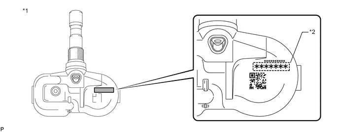
Text in Illustration *1 Tire Pressure Warning Valve and Transmitter *2 Transmitter ID (7 Digit Number) -
-
-
REGISTER TRANSMITTER ID
Note
-
When performing ID registration for the 2nd tire set, make sure that ID registration has been completed for the main tire set.
-
If ID registration for the main tire set has not been completed, it is not possible to perform ID registration for the 2nd tire set.
-
When performing ID registration for the 2nd tire set, place the tires and wheels of the 2nd tire set and main tire set close to the vehicle (less than 10 m (32.8 ft.) away from the vehicle).
Tech Tips
When registering an ID on the 2nd tire set, a tire and wheel which have an ID from the main tire set are necessary to also perform ID certification for the main tire set. If ID certification is not performed on the main tire set, DTC C2126/26 is stored by the tire pressure warning ECU and receiver.
-
When using the 2nd tire set or switching from the 2nd tire set to the main tire set after registration for the 2nd tire set is completed, switch to the appropriate set of IDs after installing the tires and wheels.
Tech Tips
-
The previously registered IDs will be cleared from memory when the registration is completed.
-
If the ID registration step is not completed within 300 seconds, ID registration will be canceled.
-
In order to perform ID registration for the 2nd set of tires, select "2nd Set" on the display screen.
-
Set the air pressure of all tires to the specified value(s).
-
Turn the engine switch off.
-
Connect the GTS to the DLC3.
-
Turn the engine switch on (IG) and the GTS on.
-
Enter the following menus: Chassis / Tire Pressure Monitor / Utility / ID Registration.
-
Perform the procedure displayed on the GTS.
-
-
CONFIRMATION OF TRANSMITTER ID REGISTRATION
Note
-
It may take up to a few minutes to update the tire pressure data. If the values are not displayed after a few minutes, perform troubleshooting according to the inspection procedure for DTCs C2121/21 to C2125/25.
-
If the IDs have not been registered, DTC C2171/71 is stored in the tire pressure warning ECU and receiver after 3 minutes or more.
-
If normal pressure values are displayed, the IDs have been registered correctly.
-
If the tire pressure values are not displayed after a few minutes, the IDs may be incorrect or the system may have a malfunction.
-
After all IDs are registered, DTC C2126/26 is stored in the tire pressure warning ECU and receiver and the tire pressure warning light blinks for 1 minute and then illuminates. When the tire pressure warning ECU and receiver successfully receives signals from all the transmitters whose IDs are stored in the ECU, DTC C2126/26 is cleared and the tire pressure warning light goes off.
-
When checking the ID registration for the 2nd tire set:
Operate the tire pressure warning reset switch and switch the IDs to the 2nd set of tires.
-
Enter the following menus: Chassis / Tire Pressure Monitor / Data List.
-
Read the "ID Tire Inflation Pressure" values.
-
Confirm that the tire pressure data of all tires is displayed on the GTS screen.
-
Reduce the tire inflation pressure of each tire 40 kPa (0.4 kgf/cm2, 5.8 psi) or more, and check that the "ID Tire Inflation Pressure" data is updated and that the actual tire inflation pressures are displayed.
-
After confirming that all of the tire inflation pressure values have been updated, adjust the tire inflation pressure to the specified value, press the tire pressure warning reset switch and perform initialization.
-
-
METHOD TO SWITCH ID
-
Method to switch IDs:
Note
-
When the tire pressure warning system is malfunctioning, be sure to perform troubleshooting for the system before performing ID switching.
-
It is not possible to perform the ID switching function while the system is being checked or during Test Mode.
-
Install the tires and wheels that use the correct IDs to the vehicle.
-
Turn the engine switch on (IG).
-
Turn the tire pressure warning reset switch on and off 3 times within 3 seconds (Press/release → press/release → press/release).
-
Check the answer-back function of the tire pressure warning light.
Tech Tips
Make sure that the tire pressure warning light illuminates for 3 seconds and turns off for 0.5 seconds 3 times.
-
-
ID switching function check:
Note
-
It may take up to 2 to 3 minutes in order to update the tire pressure data.
-
If all of the tire pressure data values are updated, ID switching has been completed.
-
After switching the IDs, DTC C2126/26 is stored in the tire pressure warning ECU and receiver and the tire pressure warning light blinks for 1 minute and then illuminates. If data from all of the tire pressure warning valve and transmitters registered in the tire pressure warning ECU and receiver is sent to the tire pressure warning ECU and receiver, DTC C2126/26 is cleared and the tire pressure warning light turns off.
-
Connect the GTS to the DLC3.
-
Enter the following menus: Chassis / Tire Pressure Monitor / Data List.
-
Reduce the tire inflation pressure of each tire 40 kPa (0.4 kgf/cm2, 5.8 psi) or more, and check that the "ID Tire Inflation Pressure" data is updated and that the actual tire inflation pressures are displayed.
-
After confirming that all of the tire inflation pressure values have been updated, adjust the tire inflation pressure to the specified value, press the tire pressure warning reset switch and perform initialization.
-
-
-
-
INITIALIZATION RELATED TO TIRE PRESSURE WARNING SYSTEM
Note
-
Initialization can be confirmed through the tire pressure warning light.
-
The order in which the data is received is random.
-
If the signals from all the wheels are received, initialization is completed.
-
Initialization is completed when the Data List "ID Tire Inflation Pressure" display shows the correct pressures.
-
Initialization is normally completed within a few minutes.
-
It may take up to a few minutes until the values are displayed. If the values are not displayed after a few minutes, perform troubleshooting according to the inspection procedure for DTCs C2121/21 to C2125/25.
-
If initialization has not been completed successfully, DTC C2177/77 is stored after the vehicle is driven at a speed of 37 km/h (23 mph) or more for 10 minutes or more.
-
During test mode (sensor check mode), the system will not change to initialization mode even if the tire pressure warning reset switch is pushed.
-
While the answer-back function for the ID switching function is operating, the system will not change to initialization mode even if the tire pressure warning reset switch is pressed.
-
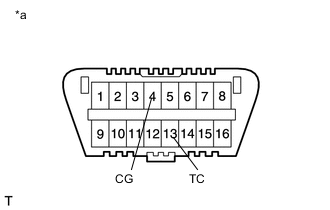
Initialization can be terminated by connecting terminals 13 (TC) and 4 (CG) of the DLC3.
Text in Illustration *a Front view of DLC3
-
BEFORE INITIALIZATION
-
Make sure that the tires are cold.
-
Set the air pressure of all tires to the specified value(s).
-
-
INITIALIZATION PROCEDURE
-
Turn the engine switch on (IG).
-
Press and hold the tire pressure warning reset switch for 3 seconds or more so that the tire pressure warning light blinks 3 times.
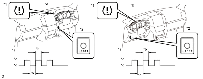
Text in Illustration *A for RHD *B for LHD *1 Tire Pressure Warning Light *2 Tire Pressure Warning Reset Switch *a Tire Pressure Warning Light Output Pattern *b 1 sec. *c ON *d OFF -
Turn the engine switch off.
-
Connect the GTS to the DLC3.
-
Turn the engine switch on (IG) and turn the GTS on.
-
Enter the following menus: Chassis / Tire Pressure Monitor / Data List.
-
Check that initialization has been completed.
-
Confirm that the tire pressure data of all tires is displayed on the GTS screen.
-
-
-
CALIBRATION RELATED TO ANTI-LOCK BRAKE SYSTEM
-
DESCRIPTION
After replacing the relevant ABS components, clear the sensor calibration data and then perform calibration.
Replacement/Adjustment Part Necessary Operation Skid control ECU (Master cylinder solenoid) Deceleration sensor zero point calibration Deceleration sensor
-
Clearing zero point calibration data
-
Deceleration sensor zero point calibration
-
-
CLEAR ZERO POINT CALIBRATION (SST CHECK WIRE)
After replacing the deceleration sensor, make sure to clear the zero point calibration data in the skid control ECU (master cylinder solenoid) and perform zero point calibration.
-
Turn the ignition switch to ON.
-
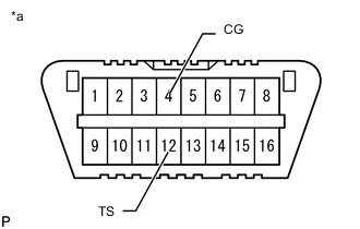
Text in Illustration *a Front view of DLC3 Using SST, connect and disconnect terminals 12 (TS) and 4 (CG) of the DLC3 4 times or more within 8 seconds.
- SST
- 09843-18040
-
Check that the ABS warning light comes on.
-
Using a check wire, perform zero point calibration of the deceleration sensor.
-
-
PERFORM ZERO POINT CALIBRATION OF DECELERATION SENSOR (SST CHECK WIRE)
After replacing the master cylinder solenoid and/or deceleration sensor, make sure to perform deceleration sensor zero point calibration.
Note
-
While obtaining the zero point, do not vibrate the vehicle by tilting, moving or shaking it. Keep it stationary and do not start the engine.
-
Choose a level surface with an inclination of less than 1°.
-
Procedures for Test Mode:
- SST
- 09843-18040
-
Turn the ignition switch off.
-
for A/T:
Move the shift lever to P.
Note
DTC 98 will be stored if the shift lever is not in P.
-
for M/T:
Pull the parking brake lever.
Note
DTC 98 will be stored if the parking brake lever is not pulled.
-
Text in Illustration *a Front view of DLC3 Using SST, connect terminals 12 (TS) and 4 (CG) of the DLC3.
-
Check that the steering wheel is centered.
-
Turn the ignition switch to ON.
-
Keep the vehicle stationary on a level surface for 2 seconds or more.
-
Check that the ABS warning light is blinking in test mode pattern (0.125 seconds on and 0.125 seconds off).
Note
The ABS warning light stays on when obtaining the zero point.
Tech Tips
-
If the ABS warning light does not blink, perform the zero point calibration again.
-
The zero point calibration is performed only once after the system enters test mode.
-
Calibration cannot be performed again until the stored data is cleared once.
-
-
-
CLEAR ZERO POINT CALIBRATION (GTS)
After replacing the deceleration sensor, make sure to clear the zero point calibration data in the skid control ECU (master cylinder solenoid) and perform zero point calibration.
-
Turn the ignition switch off.
-
Connect the GTS to the DLC3.
-
Turn the ignition switch to ON.
-
Turn the GTS on.
-
Enter the following menus: Chassis / ABS/VSC/TRC / Utility / Reset Memory.
-
Using the GTS, perform zero point calibration of the deceleration sensor.
-
-
PERFORM ZERO POINT CALIBRATION OF DECELERATION SENSOR (GTS)
After replacing the master cylinder solenoid and/or deceleration sensor, make sure to perform deceleration sensor zero point calibration.
Note
-
While obtaining the zero point, do not vibrate the vehicle by tilting, moving or shaking it. Keep it stationary and do not start the engine.
-
Choose a level surface with an inclination of less than 1°.
-
Procedures for Test Mode:
-
Turn the ignition switch off.
-
for A/T:
Move the shift lever to P.
Note
DTC C1336 will be stored if the shift lever is not in P.
-
for M/T:
Pull the parking brake lever.
Note
DTC C1336 will be stored if the parking brake lever is not pulled.
-
Check that the steering wheel is centered.
-
Connect the GTS to the DLC3.
-
Turn the ignition switch to ON.
-
Turn the GTS on.
-
Enter the following menus: Chassis / ABS/VSC/TRC / Utility / Test Mode.
-
Keep the vehicle stationary on a level surface for 2 seconds or more.
-
Check that the ABS warning light is blinking in test mode pattern (0.125 seconds on and 0.125 seconds off).
Note
The ABS warning light stays on when obtaining the zero point.
Tech Tips
-
If the ABS warning light does not blink, perform the zero point calibration again.
-
The zero point calibration is performed only once after the system enters test mode.
-
Calibration cannot be performed again until the stored data is cleared once.
-
-
-
-
-
CALIBRATION RELATED TO VEHICLE STABILITY CONTROL SYSTEM
-
DESCRIPTION
After replacing the relevant VSC components or performing a vehicle height adjustment, clear the sensor calibration data and perform calibration.
Replacement/Adjustment Part Necessary Operation Skid Control ECU (Master Cylinder Solenoid)
-
Clearing zero point calibration data
-
Yaw rate and acceleration sensor zero point calibration
Yaw Rate Sensor Assembly
-
Clearing zero point calibration data
-
Yaw rate and acceleration sensor zero point calibration
Vehicle height adjustment
-
Clearing zero point calibration data
-
Yaw rate and acceleration sensor zero point calibration
-
Steering sensor initialization
-
-
PERFORM YAW RATE AND ACCELERATION SENSOR ZERO POINT CALIBRATION AND SYSTEM INFORMATION (WHETHER VGRS IS EQUIPPED) (When Using GTS)
Note
-
While obtaining the zero points, keep the vehicle stationary and do not vibrate, tilt, move, or shake it (do not start the engine).
-
Be sure to perform this procedure on a level surface (with an inclination of less than 1%).
-
Clear the zero point calibration and system information data.
-
-
Turn the ignition switch off.
-
Check that the steering wheel is centered.
-
Check that the shift lever is in P.
-
Connect the GTS to the DLC3.
-
Turn the ignition switch to ON.
-
Turn the GTS on.
-
Enter the following menus: Chassis / ABS/VSC/TRC / Utility / Reset Memory.
-
Select the skid control ECU (master cylinder solenoid) to clear the zero point calibration data using the GTS.
-
Turn the ignition switch off.
-
-
Perform zero point calibration of the yaw rate and acceleration sensor and store the system information.
-
-
Turn the ignition switch off.
-
Check that the steering wheel is centered.
-
Check that the shift lever is in P.
Note
-
DTCs C1210 (Zero Point Calibration of Yaw Rate Sensor Undone) and C1336 (Zero Point Calibration of Acceleration Sensor Undone) are stored if the shift lever is not in P.
-
If a DTC is output that indicates zero point calibration is incomplete, repeat the procedure starting at the step for clearing the zero point calibration data and system information.
-
-
Connect the GTS to the DLC3.
-
Turn the ignition switch to ON.
-
Turn the GTS on.
-
Enter the following menus: Chassis / ABS/VSC/TRC / Utility / Test Mode.
-
Keep the vehicle stationary on a level surface for 5 seconds or more.
-
Check that the slip indicator light comes on for several seconds and then blinks in the test mode pattern (0.125 seconds on and 0.125 seconds off).
Tech Tips
-
If the slip indicator light does not blink, perform zero point calibration again.
-
The zero point calibration is performed only once after the system enters test mode.
-
Calibration cannot be performed again until the stored data is cleared.
-
-
Turn the ignition switch off and disconnect the GTS.
-
-
Check if DTC C120A (ECU Initial Setting Incomplete) is output.
Tech Tips
If DTC C120A is not output, calibration was performed successfully.
-
-
PERFORM YAW RATE AND ACCELERATION SENSOR ZERO POINT CALIBRATION AND SYSTEM INFORMATION (WHETHER VGRS IS EQUIPPED) (When Using SST Check Wire)
Note
-
While obtaining the zero points, keep the vehicle stationary and do not vibrate, tilt, move, or shake it (do not start the engine).
-
Be sure to perform this procedure on a level surface (with an inclination of less than 1%).
-
Clear the zero point calibration and system information data.
- SST
- 09843-18040
-
Turn the ignition switch off.
-
Check that the steering wheel is centered.
-
Check that the shift lever is in P.
-
Turn the ignition switch to ON.
-
Text in Illustration *a Front view of DLC3 Using SST, connect and disconnect terminals 12 (TS) and 4 (CG) of the DLC3 4 times or more within 8 seconds.
-
Check that the slip indicator light comes on.
-
Perform zero point calibration of the yaw rate and acceleration sensor and store the system information.
- SST
- 09843-18040
-
Turn the ignition switch off.
-
Check that the steering wheel is centered.
-
Check that the shift lever is in P.
Note
-
DTCs 36 (Zero Point Calibration of Yaw Rate Sensor Undone) and 98 (Zero Point Calibration of Acceleration Sensor Undone) are stored if the shift lever is not in P.
-
If a DTC is output that indicates zero point calibration is incomplete, repeat the procedure starting at the step for clearing the zero point calibration data and system information.
-
-
Text in Illustration *a Front view of DLC3 Using SST, connect terminals 12 (TS) and 4 (CG) of the DLC3.
-
Turn the ignition switch to ON.
-
Keep the vehicle stationary on a level surface for 5 seconds or more.
-
Check that the slip indicator light comes on for several seconds and then blinks in the test mode pattern (0.125 seconds on and 0.125 seconds off).
Tech Tips
-
If the slip indicator light does not blink, perform zero point calibration again.
-
The zero point calibration is performed only once after the system enters test mode.
-
Calibration cannot be performed again until the stored data is cleared.
-
-
Turn the ignition switch off and disconnect SST from the DLC3.
-
Check if DTC 13 (ECU Initial Setting Incomplete) is output.
Tech Tips
If DTC 13 is not output, calibration was performed successfully.
-
-
-
ADJUSTMENT FOR BREAK PEDAL (for LHD)
-
CHECK BRAKE PEDAL HEIGHT
-
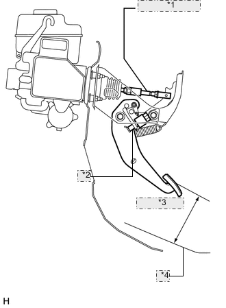
*1 Rod Operating Adapter *2 Stop Light Switch Assembly *3 Pedal Height *4 No. 2 Dash Panel Insulator Pad Check the brake pedal height.
Note
Do not adjust the pedal height. Doing so by changing the push rod length will structurally change the pedal ratio.
If the pedal height is incorrect, adjust the rod operating adapter length.
-
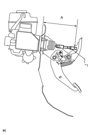
*1 Clevis Lock Nut Adjust the rod operating adapter length.
-
Remove the clip and clevis pin.
-
Loosen the clevis lock nut.
-
Adjust the rod operating adapter length by turning the pedal push rod clevis.
Standard Rod Operating Adapter Length "A" 201.7 to 202.7 mm (7.94 to 7.98 in.) -
Tighten the clevis lock nut.
-
Set the master cylinder push rod clevis in place, insert the push rod pin from the outside of the vehicle and then install a new clip.
If the pedal height is incorrect even if the rod operating adapter is adjusted, check that there is no damage in the brake pedal, brake pedal lever, brake pedal support and dash panel.
-
-
Even if there is damage, there is no problem if the reserve distance is within the standard value.
-
If necessary, replace any damaged parts.
-
- Torque:
- 26 N*m { 260 kgf*cm, 19 ft.*lbf }
-
-
-
CHECK AND ADJUST STOP LIGHT SWITCH ASSEMBLY
Tech Tips
If the pedal height is incorrect, check and adjust the stop light switch clearance.
-
Disconnect the stop light switch assembly connector from the stop light switch assembly.
-
Turn the stop light switch assembly counterclockwise and remove the stop light switch assembly.
-
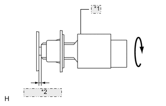
*1 Stop Light Switch *2 0.5 to 2.6 mm Insert the stop light switch assembly until the body hits the brake pedal bracket.
Note
When inserting the stop light switch assembly, support the pedal from behind so that the pedal is not pushed in.
-
Turn the stop light switch assembly a quarter turn clockwise to install it.
Tech Tips
Turning the stop light switch assembly counterclockwise loosens the switch.
-
Connect the stop light switch connector to the stop light switch assembly.
-
Check the protrusion of the rod.
-
After adjusting the pedal height, check the pedal free play.
-
-
CHECK PEDAL FREE PLAY
-
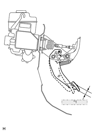
*1 Pedal Free Play Push in the pedal until the beginning of the resistance is felt. Measure the pedal free play.
-
-
CHECK PEDAL RESERVE DISTANCE
-
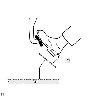
*1 Pedal Reserve Distance *2 No. 2 Dash Panel Insulator Pad Release the parking brake lever. With the engine running, depress the pedal and measure the pedal reserve distance as shown in the illustration.
With the engine running, depress the pedal and measure the pedal reserve distance as shown in the illustration.
If incorrect, troubleshoot the brake system.
-
-
-
ADJUSTMENT FOR BREAK PEDAL (for RHD)
-
CHECK BRAKE PEDAL HEIGHT
-
*1 Rod Operating Adapter *2 Stop Light Switch Assembly *3 Pedal Height *4 No. 2 Dash Panel Insulator Pad Check the brake pedal height.
Note
Do not adjust the pedal height. Doing so by changing the push rod length will structurally change the pedal ratio.
If the pedal height is incorrect, adjust the rod operating adapter length.
-
*1 Clevis Lock Nut Adjust the rod operating adapter length.
-
Remove the clip and clevis pin.
-
Loosen the clevis lock nut.
-
Adjust the rod operating adapter length by turning the pedal push rod clevis.
Standard Rod Operating Adapter Length "A" 201.7 to 202.7 mm (7.94 to 7.98 in.) -
Tighten the clevis lock nut.
-
Set the master cylinder push rod clevis in place, insert the push rod pin from the outside of the vehicle and then install a new clip. If the pedal height is incorrect even if the rod operating adapter is adjusted, check that there is no damage in the brake pedal, brake pedal lever, brake pedal support and dash panel.
-
-
Even if there is damage, there is no problem if the reserve distance is within the standard value.
-
If necessary, replace any damaged parts.
-
- Torque:
- 26 N*m { 260 kgf*cm, 19 ft.*lbf }
-
-
-
CHECK AND ADJUST STOP LIGHT SWITCH ASSEMBLY
Tech Tips
If the pedal height is incorrect, check and adjust the stop light switch clearance.
-
Disconnect the stop light switch assembly connector from the stop light switch assembly.
-
Turn the stop light switch assembly counterclockwise and remove the stop light switch assembly.
-
*1 Stop Light Switch *2 0.5 to 2.6 mm Insert the stop light switch assembly until the body hits the brake pedal bracket.
Note
When inserting the stop light switch assembly, support the pedal from behind so that the pedal is not pushed in.
-
Turn the stop light switch assembly a quarter turn clockwise to install it.
Tech Tips
Turning the stop light switch assembly counterclockwise loosens the switch.
-
Connect the stop light switch connector to the stop light switch.
-
Check the protrusion of the rod.
-
After adjusting the pedal height, check the pedal free play.
-
-
CHECK PEDAL FREE PLAY
-
*1 Pedal Free Play Push in the pedal until the beginning of the resistance is felt. Measure the pedal free play.
-
-
CHECK PEDAL RESERVE DISTANCE
-
*1 Pedal Reserve Distance *2 No. 2 Dash Panel Insulator Pad Release the parking brake lever.
With the engine running, depress the pedal and measure the pedal reserve distance as shown in the illustration.
If incorrect, troubleshoot the brake system.
-
-
-
ADJUSTMENT FOR PARKING BREAK SYSTEM
-
INSPECT PARKING BRAKE LEVER TRAVEL
-
Fully pull the parking brake lever to engage the parking brake.
-
Release the lever to disengage the parking brake.
-
Slowly pull the parking brake lever all the way, and count the number of clicks
If the parking brake lever travel is not as specified, adjust the parking brake shoe clearance and parking brake lever travel.
-
-
REMOVE REAR WHEEL
-
ADJUST PARKING BRAKE LEVER TRAVEL
-
Remove the console cup holder box sub-assembly.
-
Completely release the parking brake lever.
-
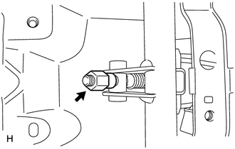
Loosen the adjusting nut to completely release the parking brake cable.
-
Temporarily install the hub nuts.
-
Remove the hole plug.
-
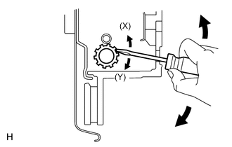
Insert an adjustment tool into the adjustment hole of the disc. Rotate the adjustment wheel in the "X" direction until the shoes are locked. Then rotate the adjustment wheel in the "Y" direction 8 notches.
-
Check that the disc can be rotated lightly. If not, rotate the adjustment wheel in the "Y" direction and check again.
-
Install the hole plug.
-
Remove the hub nuts.
-
Turn the adjusting nut until the parking brake lever travel becomes correct.
-
Operate the parking brake lever 3 to 4 times, and check the parking brake lever travel.
-
Check whether the parking brake drags or not.
-
When operating the parking brake lever, check that the brake warning light comes on.
-
Install the console cup holder box sub-assembly.
-
-
INSTALL REAR WHEEL
- Torque:
- for Aluminum Wheel
- 131 N*m { 1336 kgf*cm, 97 ft.*lbf }
- for Steel Wheel
- 209 N*m { 2131 kgf*cm, 154 ft.*lbf }
-
-
INITIALIZATION RELATED TO VGRS SYSTEM
-
STEERING ANGLE SENSOR INITIALIZATION (to obtain a tire angle (during straight-ahead driving) signal)
-
Turn the engine switch on (IG), and check that the master warning light illuminates for a few seconds.
Note
If the warning light remains on, repair the applicable system.
-
Drive the vehicle on a straight road at 35 km/h (22 mph) or more for 5 seconds or more.
Tech Tips
-
At this point, the steering wheel will still remain off-center by 5 to 10°.
-
In this step, the neutral position of the steering wheel is restored from the steering control ECU memory.
-
-
Confirm that steering angle sensor initialization is completed (using the tester).
-
Enter the VGRS menu using the tester. Select "Straight Angle Valid Flag" from "Data List". Check if the steering angle sensor has obtained a tire angle (during straight-ahead driving) signal.
Standard "Valid" is displayed on the tester screen.
-
-
Confirm that steering angle sensor initialization is completed (not using the tester).
-
Stop the vehicle (engine running).
-
Slowly turn the steering wheel from lock to lock.
-
If it turns approximately 2.7 turns, steering angle sensor initialization is completed. If it turns approximately 3.2 turns, steering angle sensor initialization is not completed.
Note
If the steering wheel turns approximately 3.2 turns, drive the vehicle on a straight road at 35 km/h (22 mph) or more for 5 seconds or more. Then confirm the initialization again.
-
-
-
VGRS SYSTEM CALIBRATION PROCEDURE (WHEN USING SST CHECK WIRE)
Note
Use this procedure to center the steering wheel if:
-
The steering actuator assembly has been replaced.
-
The steering control ECU has been replaced.
-
The steering column or steering intermediate shaft has been disconnected.
-
The steering wheel is still off-center after completing the steering angle sensor initialization.
-
FACE TIRES STRAIGHT AHEAD (Procedure A)
Note
Drive the vehicle to confirm that the steering wheel is centered.
-
CHECK DTC (Procedure B)
-
Check for DTCs.
Result Result Proceed to DTC C1591/51 is not output Procedure C DTC C1591/51 is output Procedure D
-
-
PERFORM ACTUATOR ANGLE INITIALIZATION (Procedure C)
- SST
- 09843-18040
Note
If the procedures from *1 to *2 are not completed within 1 minute, or if errors are made during these procedures, perform the initialization again from the beginning.
-
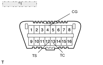
*1 Front view of DLC3: Start the engine.
-
Center the steering wheel.
-
Using SST, connect terminals 12 (TS) and 4 (CG), and 13 (TC) and 4 (CG) of the DLC3.*1
-
Disconnect SST from terminal 12 (TS) of the DLC3, and turn the steering wheel to the left 180° or more.
-
Connect SST to terminal 12 (TS) of the DLC3.
-
Disconnect SST from terminal 13 (TC) of the DLC3, and turn the steering wheel to the right 180° or more.
-
Connect SST to terminal 13 (TC) of the DLC3.*2
Tech Tips
If the master warning light comes on, DTC C1591/51 is stored.
-
Disconnect SST from the DLC3.
-
Turn the engine switch off.
-
FACE TIRES STRAIGHT AHEAD (Procedure D)
-
Confirm that the steering wheel is centered when facing the tires straight ahead.
Note
Drive the vehicle to confirm that the steering wheel is centered.
Result Result Proceed to Steering wheel is off-center Procedure E Steering wheel is centered Procedure H
-
-
UNLOCK STEERING ACTUATOR (Procedure E)
Note
Make sure the engine is not running.
-
Turn the engine switch off.
-
Disconnect the cable from the negative (-) battery terminal.
-
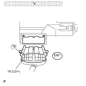
*a Rear view of wire harness connector: (to Steering Actuator ) *b 7 (LV+) Disconnect the E80 connector from the steering actuator.
-
Connect a jumper wire from terminal 7 (LV+) of the steering actuator to the positive (+) 12 V battery terminal and another jumper wire from terminal 16 (LG+) of the steering actuator to the negative (-) 12 V battery terminal.
Note
Do not apply voltage for more than 3 minutes.
-
-
STEERING CENTER ADJUSTMENT (Procedure F)
-
Center the steering wheel.
Note
If the centering of the spiral cable was not confirmed when the steering wheel was installed, confirm the centering of the spiral cable.
-
-
LOCK STEERING ACTUATOR (Procedure G)
-
Disconnect the positive (+) and negative (-) 12 V battery jumper wires from the steering actuator.
-
Connect the E80 connector to the steering actuator.
-
Connect the cable to the negative (-) battery terminal.
-
Turn the steering wheel approximately 3° to the left and right. Confirm that the reaction force can be felt.
Note
-
If the above procedures are not followed correctly, a DTC will be stored. If a DTC is stored, perform the above procedures again and then check for DTCs.
-
Perform these procedures with the engine switch off.
-
-
-
ADJUST ACTUATOR ANGLE (Procedure H)
Tech Tips
Activating and ending test mode will complete actuator angle adjustment.
- SST
- 09843-18040
-
Make sure the engine switch is off.
Note
Do not touch the steering wheel during these procedures.
-
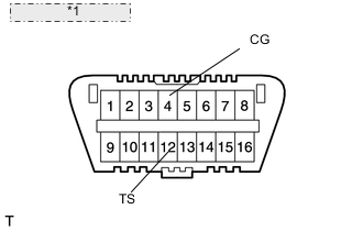
*1 Front view of DLC3: Using SST, connect terminals 12 (TS) and 4 (CG) of the DLC3.
-
Turn the engine switch on (IG).
-
Confirm that "VGRS Test Mode" is displayed on the multi-information display when test mode is activated.
Tech Tips
Wait approximately 5 seconds.
-
Turn the engine switch off.
-
Disconnect SST from terminals 12 (TS) and 4 (CG) of the DLC3.
-
Turn the engine switch on (IG) again.
-
CHECK MASTER WARNING LIGHT (Procedure I)
-
Confirm that the master warning light is off.
-
Turn the engine switch off, then on (IG).
-
Confirm that the master warning light is operating normally.
-
-
CHECK STEERING WHEEL OPERATION (Procedure J)
-
Start the engine.
-
Perform the steering angle sensor initialization.
-
Turn the steering wheel from lock to lock and check that it rotates approximately 2.7 turns.
-
Drive the vehicle and confirm that the steering wheel is centered.
-
-
-
VGRS SYSTEM CALIBRATION PROCEDURE (WHEN USING INTELLIGENT TESTER)
-
FACE TIRES STRAIGHT AHEAD (Procedure A)
Note
Drive the vehicle to confirm that the steering wheel is centered.
-
PERFORM VGRS SYSTEM CALIBRATION (Procedure B)
-
Connect the intelligent tester to the DLC3.
-
Turn the engine switch on (IG).
-
Turn the tester on.
-
Enter the following menus: Chassis / VGRS / Utility / Steering Angle Adjust.
Then, press "Next".
-
Follow the instructions on the tester, and press "Next".
Note
Press the "Next" key even if DTC C15B4/71 is output.
-
Follow the instructions on the tester, and press "Next".
-
Follow the instructions on the tester, and press "Next".
Note
Ensure that the engine switch is off.
-
Follow the instructions on the tester, and press "Next".
-
Follow the instructions on the tester, and press "Next".
Note
If the centering of the spiral cable was not confirmed when the steering wheel was installed, confirm the centering of the spiral cable.
-
Follow the instructions on the tester, and press "Next".
Note
Do not touch the steering wheel during these procedures.
-
Follow the instructions on the tester, and press "Next".
-
Follow the instructions on the tester, and press "Next".
Note
Do not touch the steering wheel during these procedures.
-
"NOW CALIBRATING" is displayed and the display switches automatically to the next screen.
Note
Do not touch the steering wheel during these procedures.
-
"Steering Angle Adjust is complete." is displayed. Then, check that the VGRS system calibration is completed normally.
-
Select "Exit" to return the display to the "MENU" screen.
-
-
CHECK MASTER WARNING LIGHT (Procedure C)
-
Confirm that the master warning light is off.
-
Turn the engine switch off.
-
Disconnect the intelligent tester from the DLC3.
-
Turn the engine switch on (IG).
-
Confirm that the master warning light is operating normally.
-
-
CHECK STEERING WHEEL OPERATION (Procedure D)
-
Start the engine.
-
Perform the steering angle sensor initialization.
-
Turn the steering wheel from lock to lock and check that it rotates approximately 2.7 turns.
-
Drive the vehicle and confirm that the steering wheel is centered.
-
-
-
-
ADJUSTMENT FOR STEERING SYSTEM
-
STEERING OFF CENTER ADJUSTMENT PROCEDURE
Tech Tips
This is the adjustment procedure for when the steering is off center.
-
Check if the steering wheel is off center.
-
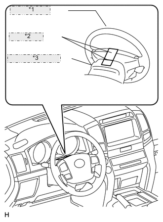
*1 Steering Wheel *2 Masking Tape *3 Steering Column Upper Cover Apply masking tape to the top center of the steering wheel and steering column upper cover.
-
Drive the vehicle in a straight line for 100 m (328 ft.) at a constant speed of 56 km/h (35 mph), and hold the steering wheel to maintain the course.
-
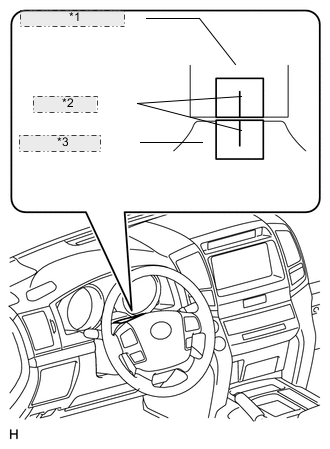
*1 Steering Column Upper Cover *2 Marked Line *3 Steering Wheel Draw a line on the masking tape as shown in the illustration.
-
Turn the steering wheel to the center position.
Tech Tips
Look at the upper surface of the steering wheel, steering spoke and SRS airbag line to find the center position.
-
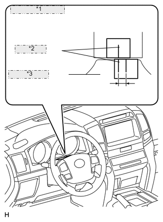
*1 Steering Column Upper Cover *2 Marked Line *3 Steering Wheel Draw a new line on the masking tape on the steering wheel as shown in the illustration.
-
Measure the distance between the 2 lines on the masking tape on the steering wheel.
-
Convert the measured distance to steering angle.
Tech Tips
-
Measured distance of 1 mm (0.0394 in.) = Steering angle of approximately 1°.
-
Make a note of the steering angle.
-
-
-
Adjust the steering angle.
-
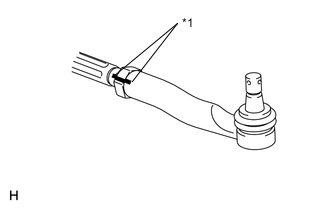
*1 Matchmark Put matchmarks on the RH and LH tie rod ends and rack ends where it can be easily seen.
-
Using a paper gauge, measure the distance from the RH and LH tie rod ends to the rack end screws.
Tech Tips
-
Measure both the RH and LH sides.
-
Make a note of the measured values.
-
-
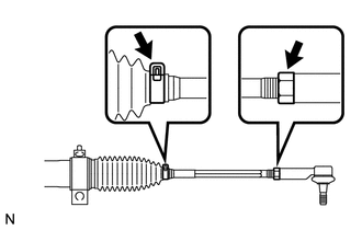
Remove the RH and LH boot clips from the rack boots.
-
Loosen the RH and LH lock nuts.
-
Turn the RH and LH rack ends by the same amount (but in different directions) according to the steering angle.
Tech Tips
One 360° turn of the rack end (1.5 mm (0.0591 in.) horizontal movement) equals 11° of steering angle.
-
Tighten the RH and LH lock nuts to the specified torque.
Note
Make sure that the difference in length between the RH and LH tie rod ends and rack end screws is within 1.5 mm (0.0591 in.).
-
Install the RH and LH boot clips.
- Torque:
- 82 N*m { 836 kgf*cm, 60 ft.*lbf }
-
-
-
-
INITIALIZATION RELATED TO PARKING ASSIST MONITOR SYSTEM (w/ Side Monitor System)
-
INITIALIZE PARKING ASSIST MONITOR SYSTEM
-
When "System initializing" is displayed on the multi-display assembly, correct the steering angle neutral point using the following method.
-
Fully turn the steering wheel to the right and left on flat ground.
Note
Memorizing the steering angle neutral point must be carried out with the engine started. Apply the parking brake, depress the brake pedal, check that the shift lever is in P, and ensure that the vehicle is not moving.
Tech Tips
The "?" button is displayed at the same time as "System initializing". If the "?" button is selected, this method is displayed.
-
-
-
-
CALIBRATION RELATED TO PARKING ASSIST MONITOR SYSTEM (w/ Side Monitor System)
-
ADJUST PARKING ASSIST MONITOR SYSTEM
-
This parking assist monitor system (w/ Side Monitor System) can be set from the diagnostic screen of the multi-display assembly.
-
If the following operations are performed, it is necessary to perform adjustments and checks on the diagnostic screen.
Part Name Operation Adjustment Item Proceed to Steering sensor
-
Removal and installation of the Steering angle sensor
-
Removal and installation of the connector of the steering sensor
Steering angle neutral point (Initialize parking assist monitor system [w/ Side Monitor System]) - Steering angle setting Procedure 2 Replacement Steering angle neutral point (Initialize parking assist monitor system [w/ Side Monitor System]) - Steering angle setting Procedure 2 Multi-media module receiver assembly Replacement Vehicle contract setting - Parking assist ECU Replacement Parking assist ECU initialization Procedure 1 Suspension, tires, etc. The vehicle height changes because of suspension or tire replacement Rear television camera optical axis (Back camera position setting) Procedure 3 Side television camera optical axis (Side camera position setting) - Rear television camera assembly
-
Replacement
-
Installation angle of the rear television camera changes because of the removal and installation of the rear television camera, etc.
Rear television camera optical axis (Back camera position setting) Procedure 3 Note
After the engine switch is turned off, the multi-media module receiver assembly requires approximately a minute to record various types of memory and settings. As a result, after turning the engine switch off, wait a minute or more before disconnecting the cable from the negative (-) battery terminal.
Tech Tips
The adjustment values stored while performing parking assist monitor system (w/ Side Monitor System) calibration are stored in the parking assist ECU.
-
-
-
PARKING ASSIST ECU INITIALIZATION (Procedure 1)
Tech Tips
Be sure to check for DTCs before performing this procedure.
-
Preparation for adjustment
-
Park the vehicle with the steering wheel centered.
-
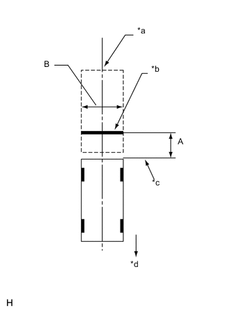
Text in Illustration *a Vehicle Center *b Target Bar for Back Camera Adjustment *c Vehicle End *d Front Side Set a target bar for optical axis adjustment of the rear television camera.
Tech Tips
Only when adjusting the optical axis of the camera, create a target bar for adjustment.
Dimension Area Specification A 825 to 835 mm (2.71 to 2.74 ft.) B 1995 to 2005 mm (6.55 to 6.58 ft.) Tech Tips
-
Set a piece of tape on the ground as the target bar for adjustment. Its width and length are 20 to 30 mm (0.787 to 1.18 in.) and 1995 to 2005 mm (6.55 to 6.58 ft.), respectively. Check the color on the multi-media module receiver assembly and choose a tape color which can be easily seen.
-
Before parking the vehicle, be sure to move the vehicle forward and in reverse to check that the tires are facing straight ahead with the steering wheel centered.
-
Check that the back door is fully closed.
-
-
Set a target bar for optical axis adjustment of the side television camera.
Tech Tips
Only when adjusting the optical axis of the camera, create a target bar for adjustment.
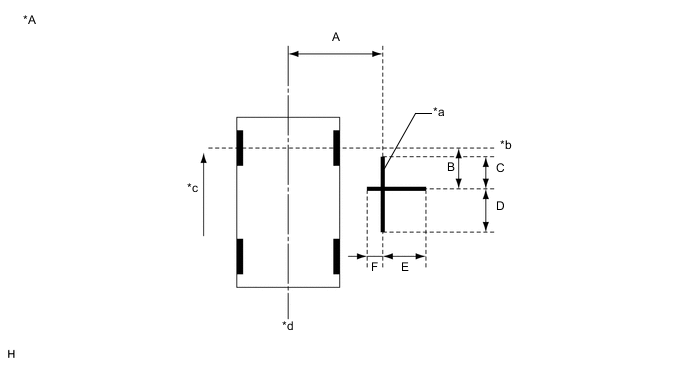
Text in Illustration *A for LHD - - *a Target Bar for Side Camera Adjustment *b Front Wheel Axis *c Front Side *d Vehicle Center 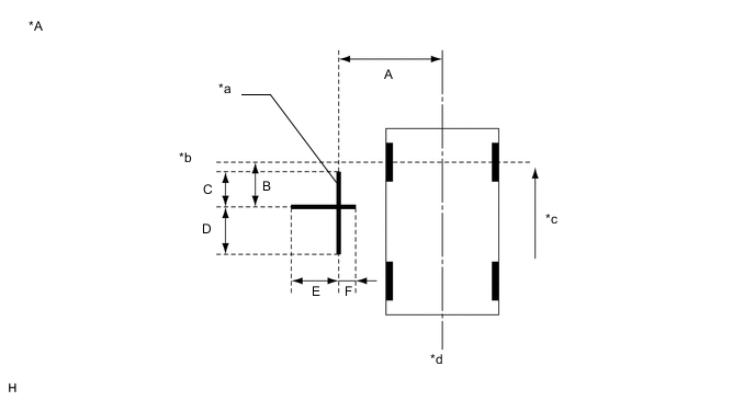
Dimension A B C D E F 1183 mm
(3.88 ft.)
1181 mm
(3.87 ft.)
500 mm
(1.64 ft.)
500 mm
(1.64 ft.)
500 mm
(1.64 ft.)
180 mm
(7.09 in.)
Text in Illustration *A for RHD - - *a Target Bar for Side Camera Adjustment *b Front Wheel Axis *c Front Side *d Vehicle Center Tech Tips
Target bars for side camera adjustment should be made with 2 pieces of 2.5 cm wide tape; one piece should be 100 cm (3.28 ft.) (C+D) and the other should be 68 cm (2.23 ft.) (E+F) long. Check the tape color on the multi-display assembly and choose a tape color which can be easily seen.
-
-
Start diagnostic mode.
Note
Alignment must be performed with the engine running. For this reason, it is necessary to apply the parking brake, depress the brake pedal, and move the shift lever into the P position, and to exercise all other necessary caution to ensure that the vehicle does not begin moving unexpectedly.
Tech Tips
The displayed items may differ depending on vehicle specifications.
-
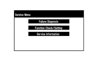
Select "Function Check/Setting" on the [Service Menu] screen.
-
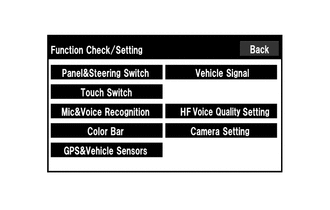
Select "Camera Setting" on the [Function Check/Setting] screen.
-
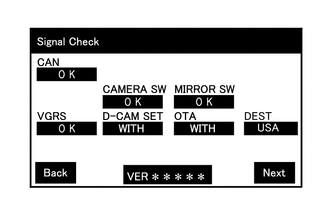
Select "Next" on the [Signal Check] screen.
Note
-
When "CHK" (red) is displayed for any items on the [Signal Check] screen, selecting "Next" will not change the screen to the [Side Camera Position Setting] screen.
-
When "CHK" (red) is displayed for any items on the [Signal Check] screen, perform inspections using the [Signal Check] screen.
Tech Tips
-
When the outer mirrors are retracted, selecting "Next" will not change the screen to the [Side Camera Position Setting] screen.
-
If the screen does not change to the [Side Camera Position Setting] screen even though the outer mirrors are extended, perform the "MIRROR SW" check on the [Signal Check] screen.
-
If the screen does not change to the [Side Camera Position Setting] screen even after "OK" (blue) is displayed as a result of the MIRROR SW check on the [Signal Check] screen, replace the parking assist ECU.
-
-
-
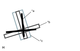
Side Camera Position Setting:
Tech Tips
Colors used on the [Side Camera Position Setting] screen
Text in Illustration *a Target Adjustment Bar for Side Camera Position Setting *b Red Frame *c Yellow Frame
-
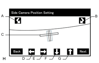
Perform the roll angle adjustment.
-
Select switches A and B to rotate C so that it is parallel to the target adjustment bar.
-
Perform the vertical and horizontal position adjustment.
-
Select the directional switches D, E, F and G to move C so that the target adjustment bar is centered in C.
-
Select "Next" to display [Side Verify Mode].
-
-
Side Verify Mode:
-

Check that the red cross and the target adjustment bar are aligned.
Tech Tips
If they are not aligned, select "Back" and perform [Side Camera Position Setting] again.
-
Select "Next" to display [Side Camera Signal Check].
-
-
Side Camera Signal Check:
-
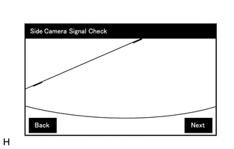
Select "Next" to store the side camera aiming adjustment value and change the screen to the [Steering Angle Setting] screen.
Tech Tips
-
When "Next" is selected, a beep will sound to confirm that the side camera aiming adjustment values have been stored.
-
The adjustment value will not be stored unless "Next" is selected.
-
-
-
Steering Angle Setting:
-
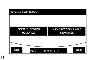
Perform the "STEERING CENTER MEMORIZE" operation.
-
Check that the steering wheel is centered, and then select "STEERING CENTER MEMORIZE".
Tech Tips
When performing removal and installation, or replacement of the television camera, steering angle adjustment is not required.
-
Perform the "MAX STEERING ANGLE MEMORIZE" operation.
-
After adjusting the steering angle neutral point, turn the steering wheel to the left and right lock positions and select "MAX STEERING ANGLE MEMORIZE". The maximum steering angle is then stored and the screen changes to the [Back Camera Position Setting] screen.
Tech Tips
-
The "Next" button does not respond until the system stores the steering angle neutral point and maximum steering angle.
-
It is also possible to start by initially turning the steering to the right side.
-
When "MAX STEERING ANGLE MEMORIZE" is selected, a beep will sound to confirm that the steering adjustment values have been stored.
-
The adjustment value will not be stored unless "MAX STEERING ANGLE MEMORIZE" is selected after turning the steering wheel side to side.
-
When "Back" is selected, the screen changes to [Side Verify Mode] without storing the set values.
-
Even if no DTCs are detected, selecting "MAX STEERING ANGLE MEMORIZE" may not cause the adjustment value to be stored if the steering sensor is malfunctioning.
-
If selecting "MAX STEERING ANGLE MEMORIZE" does not cause the adjustment value to be stored after adjusting the steering angle, replace the steering sensor.
-
-
-
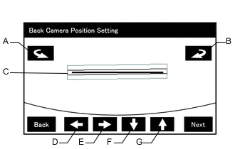
Back Camera Position Setting:
Tech Tips
-
When the back door is open, the "Back door is open. Do not use the rear view monitor when the back door is not completely closed." message will be displayed and camera position setting will not be possible.
-
If the "Back door is open. Do not use the rear view monitor when the back door is not completely closed." message is displayed even when the back door is closed, perform inspections according to Problem Symptoms Table (A back door open warning message is displayed even after back door is closed).
-
Perform the roll angle adjustment.
-
Select switches A and B to rotate C so that it is parallel to the target adjustment bar.
-
Perform the vertical and horizontal position adjustment.
-
Select the directional switches D, E, F and G to move C so that the target adjustment bar is centered in C.
-
Select the "Next" to display [Back Verify Mode].
-
-
Back Verify Mode:
-
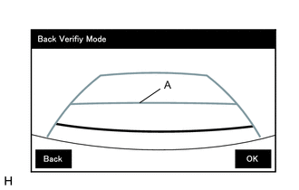
Check that A and the target adjustment bar are overlapping.
-
If the steering angle neutral point is not aligned, perform the "STEERING CENTER MEMORIZE" and "MAX STEERING ANGLE MEMORIZE" operations.
-
If A and the target adjustment bar are not aligned even if the tires are aligned straight ahead, perform the camera position setting operation.
-
Selecting "OK" will return the screen to the [Service Menu] screen, and complete the adjustment.
Tech Tips
-
The update is not completed until "OK" is selected.
-
When "OK" is selected, a beep will sound to confirm that the rear camera aiming adjustment values have been stored.
-
-
-
Finish diagnostic mode.
-
-
STEERING ANGLE SETTING (Procedure 2)
-
Preparation for adjustment
-
Park the vehicle with the steering wheel centered.
-
-
Start diagnostic mode.
Note
Alignment must be performed with the engine running. For this reason, it is necessary to apply the parking brake, depress the brake pedal, and move the shift lever into the P position, and to exercise all other necessary caution to ensure that the vehicle does not begin moving unexpectedly.
Tech Tips
The displayed items may differ depending on vehicle specifications.
-
Select "Function Check/Setting" on the [Service Menu] screen.
-
Select "Camera Setting" on the [Function Check/Setting] screen.
-
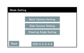
Select "Steering Angle Setting" on the [Mode Setting] screen.
Tech Tips
To select a grayed out item, select and hold the item for 2 seconds or more.
-
Select "Next" on the [Signal Check] screen.
Note
-
When "CHK" (red) is displayed for any items on the [Signal Check] screen, selecting "Next" will not change the screen to the [Steering Angle Setting] screen.
-
When "CHK" (red) is displayed for any items on the [Signal Check] screen, perform inspections using the [Signal Check] screen.
-
-
-
Steering Angle Setting:
-
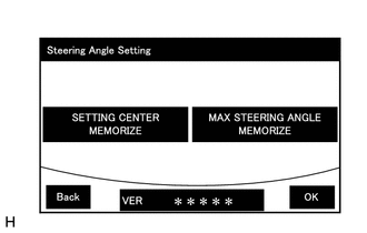
Perform the "STEERING CENTER MEMORIZE" operation.
-
Check that the steering wheel is centered, and then select "STEERING CENTER MEMORIZE".
Tech Tips
When performing removal and installation, or replacement of the television camera, steering angle adjustment is not required.
-
Perform the "MAX STEERING ANGLE MEMORIZE" operation.
-
After adjusting the steering angle neutral point, turn the steering wheel to the left and right lock positions and select "MAX STEERING ANGLE MEMORIZE". The maximum steering angle is then stored and the screen changes to the [Mode Setting] screen.
Tech Tips
-
The "Next" button does not respond until the system stores the steering angle neutral point and maximum steering angle.
-
It is also possible to start by initially turning the steering to the right side.
-
When "MAX STEERING ANGLE MEMORIZE" is selected, a beep will sound to confirm that the steering adjustment values have been stored.
-
The adjustment value will not be stored unless "MAX STEERING ANGLE MEMORIZE" is selected after turning the steering wheel side to side.
-
When "Back" is selected, the screen changes to [Signal Check] without storing the set values.
-
Even if no DTCs are detected, selecting "MAX STEERING ANGLE MEMORIZE" may not cause the adjustment value to be stored if the steering sensor is malfunctioning.
-
If selecting "MAX STEERING ANGLE MEMORIZE" does not cause the adjustment value to be stored after adjusting the steering angle, replace the steering sensor.
-
-
Select "OK" to display [Mode Setting].
-
-
Finish diagnostic mode.
-
Confirm steering angle adjustment.
Tech Tips
If the steering angle has been adjusted, confirm the steering angle adjustment on the parking assist monitor screen after finishing diagnostic mode.
-
Check on the parking assist screen that the predicted path line moves until the steering wheel is fully turned to either the left or right.
Tech Tips
If the predicted path line stops moving before the steering wheel is fully turned to either the left or right, the steering angle adjustment values have not been stored correctly. In this case, perform "STEERING CENTER MEMORIZE" and "MAX STEERING ANGLE MEMORIZE" again.
-
-
-
BACK CAMERA POSITION SETTING (Procedure 3)
Tech Tips
Be sure to check for DTCs before performing this procedure.
-
Preparation for adjustment
-
Park the vehicle with the steering wheel centered.
-
Set a target bar for optical axis adjustment of the rear television camera.
Tech Tips
Only when adjusting the optical axis of the camera, create a target bar for adjustment.
Dimension Area Specification A 825 to 835 mm (2.71 to 2.74 ft.) B 1995 to 2005 mm (6.55 to 6.58 ft.) Text in Illustration *a Vehicle Center *b Target Bar for Back Camera Adjustment *c Vehicle End *d Front Side Tech Tips
-
Set a piece of tape on the ground as the target bar for adjustment. Its width and length should be 20 to 30 mm (0.787 to 1.18 in.) and 1995 to 2005 mm (6.55 to 6.58 ft.), respectively. Check the color on the multi-display and choose a tape color which can be easily seen.
-
Before parking the vehicle, be sure to move the vehicle forward and in reverse to check that the tires are facing straight ahead with the steering wheel centered.
-
Check that the back door is fully closed.
-
-
-
Start diagnostic mode.
Note
Alignment must be performed with the engine running. For this reason, it is necessary to apply the parking brake, depress the brake pedal, and move the shift lever into the P position, and to exercise all other necessary caution to ensure that the vehicle does not begin moving unexpectedly.
Tech Tips
The displayed items may differ depending on vehicle specifications.
-
Select "Function Check/Setting" on the [Service Menu] screen.
-
Select "Camera Setting" on the [Function Check/Setting] screen.
-
Select "Back Camera Setting" on the [Mode Setting] screen.
Tech Tips
To select a grayed out item, select and hold the item for 2 seconds or more.
-
Select "Next" on the [Signal Check] screen.
Note
-
When "CHK" (red) is displayed for any items on the [Signal Check] screen, selecting "Next" will not change the screen to the [Back Camera Position Setting] screen.
-
When "CHK" (red) is displayed for any items on the [Signal Check] screen, perform inspections using the [Signal Check] screen.
-
-
-
Back Camera Position Setting:
Tech Tips
-
When the back door is open, the "Back door is open. Do not use the rear view monitor when the back door is not completely closed." message will be displayed and camera position setting will not be possible.
-
If the "Back door is open. Do not use the rear view monitor when the back door is not completely closed." message is displayed even when the back door is closed, perform inspections according to Problem Symptoms Table (A back door open warning message is displayed even after back door is closed).
-
Perform the roll angle adjustment.
-
Select switches A and B to rotate C so that it is parallel to the target adjustment bar.
-
Perform the vertical and horizontal position adjustment.
-
Select the directional switches D, E, F and G to move C so that the target adjustment bar is centered in C.
-
Select the "Next" button on the [Back Camera Position Setting] screen.
-
-
Back Verify Mode:
-
Check that A and the target adjustment bar are overlapping.
-
If the steering angle neutral point is not aligned, perform the "STEERING CENTER MEMORIZE" and "MAX STEERING ANGLE MEMORIZE" operations.
-
If A and the target adjustment bar are not aligned even if the tires are aligned straight ahead, perform the camera position setting operation.
-
Selecting "OK" will return the screen to the [Service Menu], and complete the adjustment.
Tech Tips
-
The update is not completed until "OK" is selected.
-
When "OK" is selected, a beep will sound to confirm that the rear camera aiming adjustment values have been stored.
-
-
-
Finish diagnostic mode.
-
-
-
INITIALIZATION RELATED TO PARKING ASSIST MONITOR SYSTEM (w/o Side Monitor System)
-
INITIALIZE PARKING ASSIST MONITOR SYSTEM (w/o Side Monitor System)
-
When "System initializing" is displayed on the multi-display assembly, correct the steering angle neutral point using the following method.
-
Fully turn the steering wheel to the right and left on flat ground.
Note
Memorizing the steering angle neutral point must be carried out with the engine started. Apply the parking brake, depress the brake pedal, check that the shift lever is in P, and ensure that the vehicle is not moving.
Tech Tips
The "?" button is displayed at the same time as "System initializing". If the "?" button is selected, this method is displayed.
-
-
-
-
CALIBRATION RELATED TO PARKING ASSIST MONITOR SYSTEM (w/o Side Monitor System)
-
ADJUST PARKING ASSIST MONITOR SYSTEM
-
This parking assist monitor system (w/o Side Monitor System) can be adjusted using the diagnostic screen of the display.
-
If the following operations are performed, it is necessary to perform adjustments and checks using the diagnostic screen.
Part Name Operation Adjustment Item Proceed to Steering sensor Replacement Steering angle neutral point (Initialize parking assist monitor system [w/o Side Monitor System]) - Steering angle setting Procedure 3
-
Removal and installation of the steering sensor
-
Removal and installation of the connector of the steering sensor
Steering angle neutral point (Initialize parking assist monitor system [w/o Side Monitor System]) - Steering angle setting Procedure 3 Suspension, tires, etc. The vehicle height changes because of suspension or tire replacement Rear television camera assembly optical axis (Back camera position setting) Procedure 2 Rear television camera assembly
-
Replacement
-
Installation angle of the rear television camera assembly changes because of the removal and installation of the rear television camera assembly, etc.
Rear television camera assembly optical axis (Back camera position setting) Procedure 2 Multi-media module receiver assembly Replacement Multi-media module receiver assembly Procedure 1 Note
After the engine switch is turned off, the multi-media module receiver assembly requires approximately 60 seconds to record various types of memory and settings. As a result, after turning the engine switch off, wait a minute or more before disconnecting the cable from the negative (-) battery terminal.
Tech Tips
The adjustment values stored while performing parking assist monitor system calibration are stored in the multi-media module receiver assembly.
-
-
-
MULTI-MEDIA MODULE RECEIVER ASSEMBLY (PROCEDURE 1)
Tech Tips
Be sure to check for DTCs before performing this procedure.
-
Preparation for adjustment
-
Park the vehicle with the steering wheel centered.
-
Text in Illustration *a Vehicle Center *b Target Bar for Back Camera Adjustment *c Vehicle End *d Front Set a target bar for optical axis adjustment of the rear television camera assembly.
Tech Tips
Only when adjusting the optical axis of the camera, create a target bar for adjustment.
Dimension Area Specification A 824 to 834 mm (2.70 to 2.74 ft.) B 1995 to 2005 mm (6.55 to 6.58 ft.) Tech Tips
-
Set a piece of tape on the ground as the target bar for adjustment. Its width and length should be 20 to 30 mm (0.787 to 1.18 in.) and 1995 to 2005 mm (6.55 to 6.58 ft.), respectively. Check the color on the display and choose a tape color which can be easily seen.
-
Before parking the vehicle, be sure to move the vehicle forward and in reverse to check that the tires are facing straight ahead with the steering wheel centered.
-
Check that the back door is fully closed.
-
-
-
Start diagnostic mode.
Note
The following must be carried out with the engine started. Apply the parking brake, depress the brake pedal, check that the shift lever is in P, and ensure that the vehicle is not moving.
Note
The following must be carried out with the engine started. Apply the parking brake, depress the brake pedal, check that the shift lever is in P, and ensure that the vehicle is not moving.
-
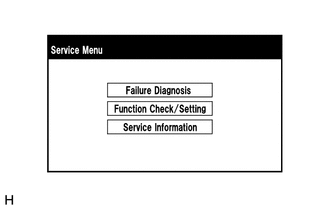
Select "Function Check/Setting" on the [Service Menu] screen.
-
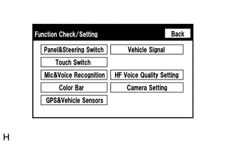
Select "Camera Setting" on the [Function Check/Setting] screen.
-
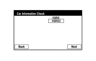
Select "Next" on the [Car Information Check] screen.
-
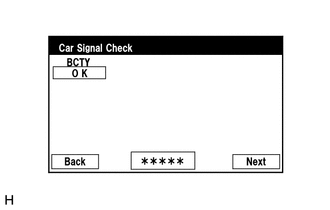
Select "Next" on the [Car Signal Check] screen.
Tech Tips
-
When "CHK" (red) is displayed for any items on the [Car Signal Check] screen, selecting "Next" will not change the screen to the "Steering Angle Setting" screen.
-
When "CHK" (red) is displayed for any items on the [Car Signal Check] screen, perform inspections using the [Car Signal Check] screen.
-
-
-
Steering Angle Setting:
-
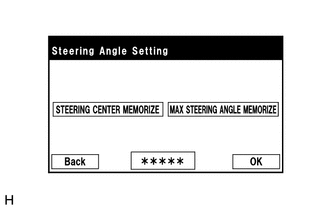
Perform the "STEERING CENTER MEMORIZE" operation.
-
Check that the steering wheel is centered, and then select "STEERING CENTER MEMORIZE".
Tech Tips
When performing removal and installation, or replacement of the rear television camera assembly, steering angle setting is not required.
-
Perform the "MAX STEERING ANGLE MEMORIZE" operation.
-
After performing the steering center memorize operation, turn the steering wheel to the left and right lock positions and select "MAX STEERING ANGLE MEMORIZE". The maximum steering angle is then stored and the screen changes to the [Back Camera Position Setting] screen.
Tech Tips
The "Next" button does not respond until the system memorizes the steering center and maximum steering wheel angle.
Tech Tips
-
It is also possible to start by initially turning the steering to the right side.
-
When "MAX STEERING ANGLE MEMORIZE" is selected, a beep will sound to confirm that the adjustment values have been stored.
-
The adjustment values will not be stored unless "MAX STEERING ANGLE MEMORIZE" is selected after turning the steering wheel from lock to lock.
-
When "Back" is selected, the screen changes to the [Car Signal Check] screen without storing any values.
-
Even if no DTCs are detected, selecting "MAX STEERING ANGLE MEMORIZE" may not cause the adjustment values to be stored if the steering sensor is malfunctioning.
-
If selecting "MAX STEERING ANGLE MEMORIZE" does not cause the adjustment value to be stored after performing the steering angle setting procedure, replace the steering sensor.
-
-
-
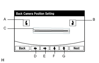
Back Camera Position Setting:
Tech Tips
-
When adjusting the camera optical axis, "Back door is open. Do not use the rear view monitor when the back door is not completely closed." is displayed even after the back door has been closed.
-
When the back door is open, the "Back door is open. Do not use the rear view monitor when the back door is not completely closed." message will be displayed and camera position setting will not be possible.
-
If the "Back door is open. Do not use the rear view monitor when the back door is not completely closed." message is displayed even when the back door is closed, perform inspections according to Problem Symptoms Table (When adjusting the camera optical axis, "Back door is open. Do not use the rear view monitor when the back door is not completely closed." is displayed even after the back door has been closed.).
-
Perform roll angle adjustment.
-
Use switches A and B to rotate C so that it is parallel to the target adjustment bar.
-
Perform vertical and horizontal position adjustment.
-
Use the directional switches D, E, F and G to move C so that the target adjustment bar is centered in C.
-
Select the "Next" button on the [Back Verify Mode] screen.
-
-
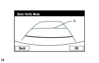
Back Verify Mode:
-
Check that A and the target adjustment bar are overlapping.
-
If the lines are not aligned, perform the "STEERING CENTER MEMORIZE" and "MAX STEERING ANGLE MEMORIZE" operations.
-
If A and the target adjustment bar are not aligned even if the tires are aligned straight ahead, perform the back camera position setting operation.
-
Selecting "OK" will return to the [Service Menu] screen, and complete the adjustment.
Tech Tips
-
The update is not completed until "OK" is selected.
-
When "OK" is selected, a beep will sound to confirm that the adjustment values have been stored.
-
The adjustment values are not stored until the beep has sounded.
-
-
-
Finish diagnostic mode.
-
Confirm steering angle adjustment.
Tech Tips
If the steering angle has been adjusted, confirm the steering angle adjustment on the parking assist monitor screen after finishing diagnosis mode.
-
Check on the parking assist screen that the predicted path line moves until the steering wheel is fully turned to either the left or right.
Tech Tips
If the predicted path line stops moving before the steering wheel is fully turned to either the left or right, the steering angle adjustment values have not been stored correctly. In this case, perform "STEERING CENTER MEMORIZE" and "MAX STEERING ANGLE MEMORIZE" again.
-
-
-
BACK CAMERA POSITION SETTING (PROCEDURE 2)
Tech Tips
Be sure to check for DTCs before performing this procedure.
-
Preparation for adjustment
-
Park the vehicle with the steering wheel centered.
-
Text in Illustration *a Vehicle Center *b Target Bar for Back Camera Position Setting *c Vehicle End *d Front Set a target bar behind the vehicle for optical axis adjustment of the rear television camera assembly (back camera position setting).
Tech Tips
Create a target bar for adjustment only when adjusting the optical axis of the camera.
Dimension Area Specification A 824 to 834 mm (2.70 to 2.74 ft.) B 1995 to 2005 mm (6.55 to 6.58 ft.) Tech Tips
-
Set a piece of tape on the ground as the target bar for adjustment. Its width and length should be 20 to 30 mm (0.787 to 1.18 in.) and 1995 to 2005 mm (6.55 to 6.58 ft.), respectively. Check the color on the multi-media module receiver assembly and choose a tape color which can be easily seen.
-
Before parking the vehicle, be sure to move the vehicle forward and in reverse to check that the tires are facing straight ahead with the steering wheel centered.
-
Check that the back door is fully closed.
-
-
-
Start diagnostic mode.
Note
The following must be carried out with the engine started. Apply the parking brake, depress the brake pedal, check that the shift lever is in P, and ensure that the vehicle is not moving.
-
Select "Function Check/Setting" on the [Service Menu] screen.
-
Select "Camera Setting" on the [Function Check/Setting] screen.
-
Select "Next" on the [Car Information Check] screen.
-
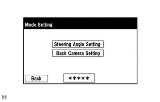
Select "Back Camera Setting" on the [Mode Setting] screen.
Tech Tips
To select a grayed out item, select and hold the item for 2 seconds or more.
-
Select "Next" on the [Car Signal Check] screen.
Tech Tips
-
When "CHK" (red) is displayed for any items on the [Car Signal Check] screen, selecting "Next" will not change the screen to the [Back Camera Position Setting] screen.
-
When "CHK" (red) is displayed for any items on the [Car Signal Check] screen, perform inspections using the [Car Signal Check] screen.
-
-
-
Back Camera Position Setting:
Tech Tips
-
When the back door is open, the "Back door is open. Do not use the rear view monitor when the back door is not completely closed." message will be displayed and camera position setting will not be possible.
-
If the "Back door is open. Do not use the rear view monitor when the back door is not completely closed." message is displayed even when the back door is closed, perform inspections according to Problem Symptoms Table (When adjusting the camera optical axis, "Back door is open. Do not use the rear view monitor when the back door is not completely closed." is displayed even after the back door has been closed.).
-
Perform roll angle adjustment.
-
Use switches A and B to rotate C so that it is parallel to the target adjustment bar.
-
Perform vertical and horizontal position adjustment.
-
Use the directional switches D, E, F and G to move C so that the target adjustment bar is centered in C.
-
Select the "Next" button on the [Back Verify Mode] screen.
-
-
Back Verify Mode:
-
Check that A and the target adjustment bar are overlapping.
-
If the lines are not aligned, perform the "STEERING CENTER MEMORIZE" and "MAX STEERING ANGLE MEMORIZE" operations.
-
If A and the target adjustment bar are not aligned even if the tires are aligned straight ahead, perform the back camera position setting operation.
-
Selecting "OK" will return to the [Service Menu], and complete the adjustment.
Tech Tips
-
The update is not completed until "OK" is selected.
-
When "OK" is selected, a beep will sound to confirm that the adjustment values have been stored.
-
The adjustment values are not stored until the beep has sounded.
-
-
-
Finish diagnostic mode.
-
-
Steering Angle Setting (PROCEDURE 3)
Tech Tips
If the vehicle width extension lines and predicted path lines are not aligned when the steering wheel is centered, or if the predicted path line does not move before the steering wheel is fully turned to either the left or right, perform Steering Angle Setting.
-
Center the steering wheel and stop the vehicle.
-
Start diagnostic mode.
Note
The following must be carried out with the engine started. Apply the parking brake, depress the brake pedal, check that the shift lever is in P, and ensure that the vehicle is not moving.
-
Select "Function Check/Setting" on the [Service Menu] screen.
-
Select "Camera Setting" on the [Function Check/Setting] screen.
-
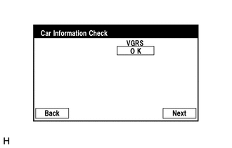
Select "Next" on the [Car Information Check] screen.
-
Select "Steering Angle Setting" on the [Mode Setting] screen.
Tech Tips
To select a grayed out item, select and hold the item for 2 seconds or more.
-
Select "Next" on the [Car Signal Check] screen to display the [Steering Angle Setting] screen.
Tech Tips
-
When "CHK" (red) is displayed for any items on the [Car Signal Check] screen, selecting "Next" will not change the screen to the [Steering Angle Setting] screen.
-
When "CHK" is displayed for any items on the [Car Signal Check] screen, perform inspections using the [Car Signal Check] screen.
-
-
-
Steering Angle Setting:
-
Check that the steering wheel is centered (approximately +/- 5 degrees or less) and select "STEERING CENTER MEMORIZE".
-
After the centered steering position is memorized, turn the steering wheel to the left and then to the right full lock positions and select "MAX STEERING ANGLE MEMORIZE".
Tech Tips
It is also possible to start by initially turning the steering wheel to the right side.
-
Select "MAX STEERING ANGLE MEMORIZE" to store the steering angle adjustment value and change the screen to the [Mode Setting] screen.
Tech Tips
-
When "MAX STEERING ANGLE MEMORIZE" is selected, a beep will sound to confirm that the steering angle adjustment values have been stored.
-
The adjustment values will not be stored unless "MAX STEERING ANGLE MEMORIZE" is selected.
-
When "Back" is selected, the screen changes to [Car Signal Check] without storing the set values.
-
If the "Steering Angle Setting"s have not been adjusted, selecting "MAX STEERING ANGLE MEMORIZE" will not cause the adjustment values to be stored.
-
Even if no DTCs are detected, selecting "MAX STEERING ANGLE MEMORIZE" may not cause the adjustment value to be stored if the steering sensor is malfunctioning.
-
If selecting "MAX STEERING ANGLE MEMORIZE" does not cause the adjustment value to be stored after adjusting the steering angle, replace the steering sensor.
-
-
Finish diagnostic mode.
-
Confirm steering angle adjustment.
Tech Tips
If the steering angle has been adjusted, confirm the steering angle adjustment on the parking assist monitor screen after finishing diagnosis mode.
-
Check on the parking assist screen that the predicted path line moves until the steering wheel is fully turned to either the left or right.
Tech Tips
If the predicted path line stops moving before the steering wheel is fully turned to either the left or right, the steering angle adjustment values have not been stored correctly. In this case, perform "STEERING CENTER MEMORIZE" and "MAX STEERING ANGLE MEMORIZE" again.
-
-
-
-
-
INITIALIZATION RELATED TO SIDE MONITOR SYSTEM
-
INITIALIZE SIDE MONITOR SYSTEM
-
When "System initializing" is displayed on the multi-display assembly, correct the steering angle neutral point using the following method.
-
Fully turn the steering wheel to the right and left on the flat ground.
Note
Memorizing the steering angle neutral point must be carried out with the engine started. Apply the parking brake, depress the brake pedal, move the shift lever to P and make sure that the vehicle is not moving.
Tech Tips
"?" button is displayed at the same time as "System initializing". If the "?" button is selected, this method is displayed.
-
-
-
-
CALIBRATION RELATED TO SIDE MONITOR SYSTEM
-
ADJUST PARKING ASSIST MONITOR SYSTEM
-
This side monitor system can be set from the diagnostic screen of the multi-display assembly.
-
If the following operations are performed, it is necessary to perform adjustments and checks on the diagnostic screen.
Part Name Operation Adjustment Item Proceed to Steering sensor
-
Removal and installation of the Steering angle sensor
-
Removal and installation of the connector of the Steering angle sensor
-
Replacement
Steering angle neutral point - Steering angle setting - Multi-media module receiver assembly Replacement Vehicle contract setting - Parking assist ECU Replacement Parking assist ECU initialization - Suspension, tires, etc. The vehicle height changes because of suspension or tire replacement Rear television camera optical axis (Camera position setting) - Side television camera optical axis (Camera position setting) Procedure 1 Side television camera assembly
-
Replacement
-
Installation angle of the side television camera changes because of the removal and installation of the side television camera, etc.
Side television camera optical axis (Camera position setting) Procedure 1 Outer rear view mirror assembly Replacement Side television camera optical axis (Camera position setting) Procedure 1 Note
After the engine switch is turned off, the multi-media module receiver assembly requires approximately 60 seconds to record various types of memory and settings. As a result, after turning the engine switch off, wait a minute or more before disconnecting the cable from the negative (-) battery terminal.
Tech Tips
The adjustment values stored while performing side monitor system calibration are stored in the parking assist ECU.
-
-
-
SIDE CAMERA SETTING (Procedure 1)
Tech Tips
Be sure to check for DTCs before performing this procedure.
-
Preparation for adjustment
-
Park the vehicle with the steering wheel centered.
-
Text in Illustration *a Vehicle Center *b Target Bar for Back Camera Adjustment *c Vehicle End *d Front Side Set a target bar for optical axis adjustment of the rear television camera.
Tech Tips
Only when adjusting the optical axis of the camera, create a target bar for adjustment.
Dimension Area Specification A 825 to 835 mm (2.71 to 2.74 ft.) B 1995 to 2005 mm (6.45 to 6.58 ft.) Tech Tips
-
Set a piece of tape on the ground as the target bar for adjustment. Its width and length are 20 to 30 mm (0.79 to 1.18 in.) and 1995 to 2005 mm (6.55 to 6.58 ft.), respectively. Check the color on the multi-display assembly and choose a tape color which can be easily seen.
-
Before parking the vehicle, be sure to move the vehicle forward and in reverse to check that the tires are facing straight ahead with the steering wheel centered.
-
Check that the back door is fully closed.
-
-
Set a target bar for optical axis adjustment of the side television camera.
Tech Tips
Only when adjusting the optical axis of the camera, create a target bar for adjustment.
Text in Illustration *A for LHD - - *a Target Bar for Side Camera Adjustment *b Front Wheel Axis *c Front Side *d Vehicle Center
Dimension A B C D E F 1183 mm
(3.88 ft.)
1181 mm
(3.87 ft.)
500 mm
(1.64 ft.)
500 mm
(1.64 ft.)
500 mm
(1.64 ft.)
180 mm
(7.09 in.)
Text in Illustration *A for RHD - - *a Target Bar for Side Camera Adjustment *b Front Wheel Axis *c Front Side *d Vehicle Center Tech Tips
Target bars for side camera adjustment should be made with 2 pieces of 2.5 cm wide tape; one piece should be 100 cm (3.28 ft.) (C+D) and the other should be 68 cm (2.23 ft.) (E+F) long. Check the tape color on the multi-media module receiver assembly and choose a tape color which can be easily seen.
-
-
Start diagnostic mode.
Note
Alignment must be performed with the engine running. For this reason, it is necessary to apply the parking brake, depress the brake pedal, and move the shift lever into the P position, and to exercise all other necessary caution to ensure that the vehicle does not begin moving unexpectedly.
Tech Tips
The displayed items may differ depending on vehicle specifications.
-
Select "Function Check/Setting" on the [Service Menu] screen.
-
Select "Camera Setting" on the [Function Check/Setting] screen.
-
Select "Side Camera Setting" on the [Mode Setting] screen.
Tech Tips
To select a grayed out item, select and hold the item for 2 seconds or more.
-
Select "Next" on the [Signal Check] screen.
Note
-
When "CHK" (red) is displayed for any items on the [Signal Check] screen, selecting "Next" will not change the screen to the [Side Camera Position Setting] screen.
-
When "CHK" (red) is displayed for any items on the [Signal Check] screen, perform inspections using the [Signal Check] screen.
Tech Tips
-
When the outer mirrors are retracted, selecting "Next" will not change the screen to the [Side Camera Position Setting] screen.
-
If the screen does not change to the [Side Camera Position Setting] screen even though the outer mirrors are extended, perform the "MIRROR SW" check on the [Signal Check] screen.
-
If the screen does not change to the [Side Camera Position Setting] screen even after "OK" (blue) is displayed as a result of the MIRROR SW check on the [Signal Check] screen, replace the parking assist ECU.
-
-
-
Side Camera Position Setting:
Tech Tips
Colors used on the [Side Camera Position Setting] screen
Text in Illustration *a Target Adjustment Bar for Side Camera Position Setting *b Red Frame *c Yellow Frame
-
Perform the roll angle adjustment.
-
Select switches A and B to rotate C so that it is parallel to the target adjustment bar.
-
Perform the vertical and horizontal position adjustment.
-
Select the directional switches D, E, F and G to move C so that the target adjustment bar is centered in C.
-
Select "Next" to display [Side Verify Mode].
-
-
Side Verify Mode:
-
Check that the red cross and the target adjustment bar are aligned.
Tech Tips
If they are not aligned, select "Back" and perform [Side Camera Position Setting] again.
-
Select "Next" to display [Side Camera Signal Check].
-
-
Side Camera Signal Check:
-
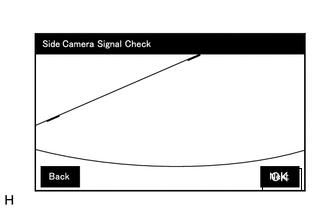
Select "OK" to store the side camera aiming adjustment value and change the screen to the [Service Menu] screen.
Tech Tips
-
When "OK" is selected, a beep will sound to confirm that the side camera aiming adjustment values have been stored.
-
The adjustment value will not be stored unless "Back" is selected.
-
-
-
Finish diagnostic mode.
-
-
-
REGISTRATION RELATED TO WIRELESS DOOR LOCK CONTROL SYSTEM (w/o Entry and Start System)
-
DESCRIPTION OF CODE REGISTRATION
Tech Tips
-
Recognition code registration is necessary when replacing the door control transmitter or door control receiver.
-
Add mode is used to register new recognition codes while still retaining codes already registered. This mode is used when a new transmitter is added. If the number of registered codes exceeds 6, the previously registered codes will be cleared in order, starting from the first registered code.
-
Rewrite mode is used to clear all the previously registered recognition codes in order to register new recognition codes. This mode is used when the transmitter or door control receiver is replaced with a new one.
-
Confirmation mode is used to confirm how many recognition codes have already been registered before registering any additional recognition codes.
-
Prohibition mode is used to clear all the registered codes and disables the wireless door lock function. This mode is used when the transmitter is lost.*
-
*: The system can be manually switched to prohibition mode (for Middle East).
-
The registration procedures must be performed in order.
-
-
REGISTER RECOGNITION CODE (USING INTELLIGENT TESTER)
Tech Tips
For detailed procedures, refer to the prompts on the intelligent tester screen. The number of currently registered codes can be checked on the first screen of Wireless Code Registration.
-
Turn the ignition switch to ON.
-
Enter the following menus: Body / Main Body / Utility / Wireless Code Registration.
-
Press both the lock and unlock switches at the same time for 1 to 1.5 seconds.
-
Press either switch for more than 1 second within 3 seconds.
-
Check the response to the registration completion.
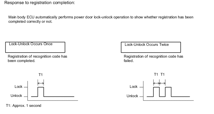
Tech Tips
-
If the lock-unlock operation occurs twice, the registration of the recognition code has failed. Perform the registration procedures again from the beginning.
-
If registering another transmitter, repeat the procedures after the intelligent tester operation. All 6 recognition codes can be registered consecutively.
-
-
Perform either of the following to complete the registration of the recognition codes:
-
Use the intelligent tester to send a completion command.
-
Disconnect the intelligent tester.
-
-
-
REGISTER RECOGNITION CODE (USING SWITCH OPERATION)
-
Make sure the following conditions are met.
-
No key is inserted in the ignition key cylinder.
-
The driver side door is open (the other doors are closed).
-
The driver side door is unlocked.
-
-
Insert and remove the key into/from the ignition key cylinder twice (Insert → Remove → Insert → Remove) within 5 seconds.
Tech Tips
The procedure should end with the key removed.
-
Perform the following operations within 40 seconds.
-
Close and open the driver side door twice (Close → Open → Close → Open).
Tech Tips
The procedure should end with the door open.
-
Insert and remove the key into/from the ignition key cylinder (Insert → Remove).
Tech Tips
The procedure should end with the key removed.
-
Close and open the driver side door twice (Close → Open → Close → Open).
Tech Tips
The procedure should end with the door open.
-
Insert the key into the ignition key cylinder and close all the doors.
-
-
-
Perform the following operations within 40 seconds.
-
Turn the ignition switch to ON and then off at approximately 1 second intervals. Operate the ignition switch according to the number of times shown below.
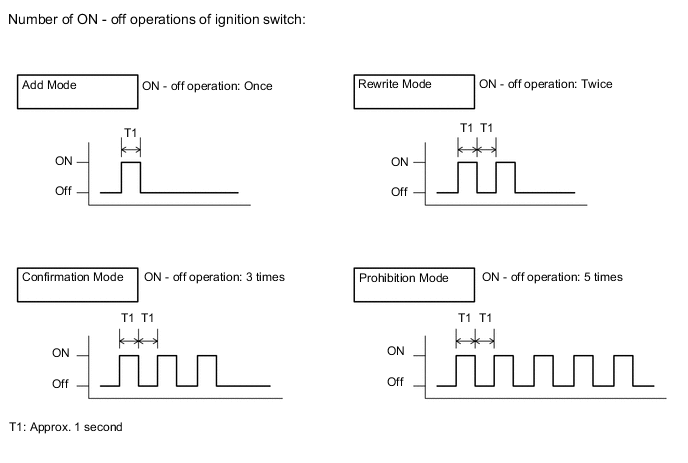
Tech Tips
If the number of ignition switch ON - off operations is 0, 4, or 6 or more, there will be no response (power door lock and unlock operation) to show which mode has been selected.
-
Remove the key from the ignition key cylinder.
-
-
Check that the response begins within 5 seconds after completing the above step, and that the response matches the selected mode.
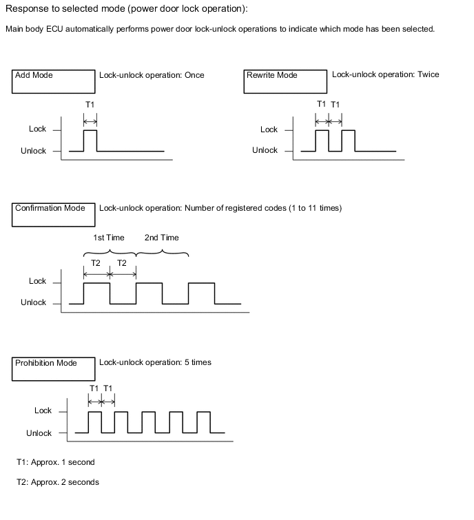
Note
After the system has been set to prohibition mode, enter confirmation mode and check that the number of registered keys is 0.
Tech Tips
-
In confirmation mode, the lock-unlock operation will occur once for each recognition code that has been registered. For example, if 2 recognition codes have been registered, the lock-unlock operation will occur twice.
-
In confirmation mode, if no recognition codes have been registered, the lock-unlock operation will occur 11 times.
-
If confirmation mode or prohibition mode is selected, the operation ends after the response to the selected mode completes.
-
-
If add mode or rewrite mode is selected, perform the following procedures.
-
Press a single switch (lock or unlock) within 5 seconds.
-
Check that the response begins within 3 seconds after completing the above step, and that the response indicates that registration has been completed correctly.
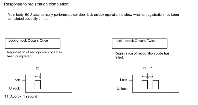
Tech Tips
-
If the lock-unlock operation occurs twice, the registration of the recognition code has failed. Perform the registration procedures again from the beginning.
-
If registering another transmitter, repeat the procedures after the mode selection response confirmation. All 6 recognition codes can be registered consecutively.
-
-
Perform either of the following to complete the registration of the recognition codes:
-
Open a door.
-
Insert the key into the ignition key cylinder.
-
-
-
-
INITIALIZATION RELATED TO POWER WINDOW CONTROL SYSTEM (Models with Jam Protection Function on 4 Windows)
-
INITIALIZE POWER WINDOW CONTROL SYSTEM (POWER WINDOW REGULATOR MOTOR [ALL DOORS])
CAUTION:
When the power window regulator motor is reinstalled or replaced, the power window control system must be initialized. Functions such as the auto up/down, jam protection and key-off do not operate if the initialization is not performed.
Tech Tips
When the battery is replaced, it is not necessary to initialize the power window regulator motor.
Note
-
When the power window regulator motor is replaced, DTC B2313 is output. Clear the DTC after the initialization.
-
When performing initialization, do not perform any other procedures.
-
After a door glass or a door glass run has been replaced, the jam protection function may operate unexpectedly when the auto up function is used, due to detection of a value different from the operation learned value of the door glass movement speed. In such cases, the auto up function can be resumed by repeating the following operation at least 5 times:
-
Open the power window by fully pushing down the power window switch.
-
Close the power window by fully pulling up the power window switch and holding it at the auto up position.
-
If the initialization is not completed properly, the LIN communication system may have a malfunction.
-
Initialization procedures when replacing the power window regulator motor with a new one:
-
Connect the battery and turn the ignition switch ON.
-
Fully open the window by fully pushing the power window switch, and hold the switch for 1 second or more after the window is fully opened.
-
Fully close the power window by fully pulling the power window switch, and hold the switch for 1 second or more after the window is fully closed to reset the glass position.
-
-
Initialization procedures when removing/installing the power window regulator motor:
-
Connect the battery and turn the ignition switch ON.
-
Fully close the power window by fully pulling the power window switch, and hold the switch for 6 seconds or more after the window is fully closed (if the power window does not move or stops halfway even when the switch is fully pulled, release the switch and fully pull it again).
-
Fully open the window by pushing down the power window switch, and hold the switch for 1 second or more after the window is fully opened.
-
Release the power window switch. Then fully push and hold the switch for 4 seconds or more.
-
Fully close the power window by fully pulling the power window switch, and hold the switch for 1 second or more after the window is fully closed to reset the glass position and complete the initialization.
-
-
Initialization procedures when the power window does not fully open:
-
Connect the battery and turn the ignition switch ON.
-
Fully close the power window by fully pulling the power window switch, and hold the switch for 6 seconds or more after the window is fully closed (if the power window does not move or stops halfway even when the switch is fully pulled, release the switch and fully pull it again).
-
Fully open the window by pushing down the power window switch, and hold the switch for 1 second or more after the window is fully opened.
-
Release the power window switch. Then fully push and hold the switch 4 seconds or more.
-
Fully close the power window by fully pulling the power window switch, and hold the switch 1 second or more after the window is fully closed to reset the glass position and complete the initialization.
-
-
-
-
INITIALIZATION RELATED TO AIR CONDITIONING SYSTEM (for Automatic Air Conditioning System)
-
INITIALIZATION SERVO MOTOR
-
Turn the engine switch off.
-
Connect the intelligent tester to the DLC3.
-
Turn the engine switch on (IG).
-
Press the blower OFF switch.
-
Turn the intelligent tester on.
-
Enter the following menus: Body Electrical / Air Conditioner / Utility / Servomotor Initialization.
-
According to the intelligent tester display, perform servomotor initialization.
Tech Tips
During initialization, the AUTO indicator light comes on, and then goes off when initialization has finished.
-
According to the intelligent tester display, select the "Exit" switch to finish initialization.
-
-
-
INITIALIZATION RELATED TO POWER WINDOW CONTROL SYSTEM (for Models with Jam Protection Function on Driver Door Window Only)
-
INITIALIZE POWER WINDOW CONTROL SYSTEM (POWER WINDOW REGULATOR MOTOR (for Driver Side))
CAUTION:
When the power window regulator motor is reinstalled or replaced, the power window control system must be initialized. Functions such as the auto up/down, jam protection and key-off do not operate if the initialization is not performed.
Tech Tips
When the battery is replaced, it is not necessary to initialize the power window regulator motor.
Note
-
When the power window regulator motor is replaced, DTC B2313 is output. Clear the DTC after the initialization.
-
When performing initialization, do not perform any other procedures.
-
After a door glass or a door glass run has been replaced, the jam protection function may operate unexpectedly when the auto up function is used, due to detection of a value different from the operation learned value of the door glass movement speed. In such cases, the auto up function can be resumed by repeating the following operation at least 5 times:
-
Open the power window by fully pushing down the power window switch.
-
Close the power window by fully pulling up the power window switch and holding it at the auto up position.
-
If the initialization is not completed properly, the LIN communication system may have a malfunction.
-
Initialization procedures when replacing the power window regulator motor with a new one:
-
Connect the battery and turn the ignition switch ON (at this time, the LED on the power window switch blinks to indicate that it is ready for initialization).
-
Fully open the window by fully pushing the power window switch, and hold the switch for 1 second or more after the window is fully opened.
-
Fully close the power window by fully pulling the power window switch, and hold the switch for 1 second or more after the window is fully closed to reset the glass position. The LED on the power window switch stops blinking and illuminated to indicate that the initialization is complete.
-
-
Initialization procedures when removing/installing the power window regulator motor:
-
Connect the battery and turn the ignition switch ON.
-
Fully close the power window by fully pulling the power window switch, and hold the switch for 6 seconds or more after the window is fully closed (if the power window does not move or stops halfway even when the switch is fully pulled, release the switch and fully pull it again).
-
Fully open the window by pushing down the power window switch, and hold the switch for 1 second or more after the window is fully opened.
-
Release the power window switch. Then fully push and hold the switch for 4 seconds or more.
-
Fully close the power window by fully pulling the power window switch, and hold the switch for 1 second or more after the window is fully closed to reset the glass position and complete the initialization.
-
-
Initialization procedures when the power window does not fully open:
-
Connect the battery and turn the ignition switch ON.
-
Fully close the power window by fully pulling the power window switch, and hold the switch for 6 seconds or more after the window is fully closed (if the power window does not move or stops halfway even when the switch is fully pulled, release the switch and fully pull it again).
-
Fully open the window by pushing down the power window switch, and hold the switch for 1 second or more after the window is fully opened.
-
Release the power window switch. Then fully push and hold the switch 4 seconds or more.
-
Fully close the power window by fully pulling the power window switch, and hold the switch 1 second or more after the window is fully closed to reset the glass position and complete the initialization.
-
-
-
-
INITIALIZATION RELATED TO INNER REAR VIEW MIRROR
-
SELECT COMPASS DISPLAY MODE
-
The compass switch allows you to select the Display or Non-display mode of the compass.
-
-
SET ZONE
-
Deviation between the "magnetic north" and "actual north" differs depending on the location. Therefore, adjustment of the magnetism is required. Because the magnetic condition differs depending on the area where the vehicle is used, it is necessary for each user to set the zone (refer to Compass Zone Map). The zone setting can be changed using the compass switch of the inner mirror.
-
-
PERFORM CALIBRATION
-
Because each vehicle has its own magnetic field, calibration should be performed for each individual vehicle. This compass function is used when storing the record of the vehicle's magnetic field.
-
-
WHEN COMPASS IS MAGNETIZED
-
The compass could be magnetized during shipping by vessels or freight cars. Therefore, ensure that calibration is performed properly before delivery. If driving the vehicle in a circle several times does not complete the calibration procedure, there may be a compass magnetization problem.

*1 "AUTO" Switch *2 Compass Display
-
-
Deviation Calibration Procedure
-
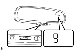
Turn the ignition switch to the "IG-ON" position and push and hold the "AUTO" switch for 6 seconds until the zone number appears on the display.
Tech Tips
Pushing the "AUTO" switch for 3 seconds turns on or off the compass display.
-
Push the "AUTO" switch to select the number of the zone where the vehicle is located. See the map for zone reference.
-
-
Circling Calibration Procedure
-
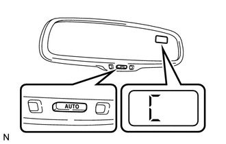
Start the engine and push and hold the "AUTO" switch for 9 seconds until "C" appears on the display.
-
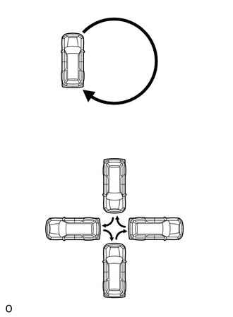
Drive the vehicle slowly at 8 km/h (5 mph) or lower in a circle. If there is not enough space to drive in a circle, turn the car around in the following manner, doing two three-point turns in succession. After driving in 1 to 3 circles in the above method, calibration is completed with the direction is shown on the display.
Tech Tips
-
Do not perform calibration of the compass in a place where the earth's magnetic field is subject to interference by artificial magnetic fields (underground parking, under a steel tower, between buildings, roof parking, near a crossing, near a large vehicle, etc.).
-
During calibration, do not operate electric systems (sliding roof, power windows, etc.) as they may interfere with the calibration.
-
-
-
-
INITIALIZATION RELATED TO SLIDING ROOF SYSTEM
-
INITIALIZE SLIDING ROOF DRIVE GEAR
Note
-
When the sliding roof glass is replaced or removed and installed, or the drive gear assembly is replaced, the sliding roof drive gear requires initialization (pulse sensor initial position setting), as the glass position cannot be determined. If initialization is not performed, the auto slide open and close/tilt up and down function may not operate, or the sliding roof may move in reverse or become misaligned.
-
During initialization, do not apply a physical shock, such as opening/closing a door or driving the vehicle at 5 km/h (3.10 mph) or more, to the vehicle and do not perform the following electrical operations:
-
Cranking the engine
-
Turning the engine switch from on (IG) to off
-
Operating the power window switches
-
Operating the window defogger switch
-
Operating the blower switch
-
Locking/Unlocking the door
-
Operating the headlight dimmer switch
Tech Tips
When the cable is disconnected and reconnected to the negative (-) battery terminal or the drive gear connector is disconnected and reconnected, the sliding roof drive gear (pulse sensor initial position setting) initialization is not necessary.
-
Perform initialization according to the table below.
Condition of Sliding Roof Proceed to Auto slide open and close/tilt up and down function does not operate Procedure A Sliding roof moves in reverse direction during tilt down operation Procedure B Sliding roof moves in reverse direction during slide close operation Procedure C
-
Procedure A
-
Turn the engine switch to ON.
-
Open the sliding roof to the fully tilt up position.
-
Press and hold the UP switch to perform the following operations: tilt up → approximately 10 second pause → tilt down → slide open → slide close.
Note
Make sure not to release the switch during the initialization. If the switch is released, perform the initialization again.
-
Continue to hold the switch for 1 second or more after the sliding roof stops in the fully closed position, and then release it.
-
The initialization is completed.
-
Procedure B
-
Turn the engine switch to ON.
-
Press the UP switch until the sliding roof stops.
Tech Tips
If the glass becomes misaligned or does not fully tilt up, perform the following operations:
-
Operate the CLOSE switch until the sliding roof stops moving.
-
Operate the UP switch until the sliding roof stops moving, then proceed to the next step.
-
-
Release the switch.
-
Press and hold the UP switch to perform the following operations: tilt up → approximately 10 second pause → tilt down → slide open → slide close.
Note
Make sure not to release the switch during the initialization. If the switch is released, perform the initialization again.
-
Continue to hold the switch for 1 second or more after the sliding roof stops in the fully closed position, and then release it.
-
The initialization is completed.
-
Procedure C
-
Turn the engine switch to ON.
-
Press and hold the CLOSE switch to perform the following operations: slide close → move in reverse direction → 10 second pause → slide close → tilt up → tilt down.
Note
Make sure not to release the switch during the initialization. If the switch is released, perform the initialization again.
-
Continue to hold the switch for 1 second or more after the sliding roof stops in the fully closed position, and then release it.
-
Check if the auto function is operative.
-
-
-
-
INITIALIZATION RELATED TO POWER BACK DOOR SYSTEM
-
RESET BACK DOOR CLOSE POSITION
Note
Perform initialization of the power back door system (power back door unit assembly [power back door ECU] initialization) if one of the following is performed: 1) The cable is disconnected from the negative (-) battery terminal; 2) a wire harness, the power back door unit assembly (power back door ECU) or back door lock assembly is replaced or removed/installed; or 3) the ECU-B2 fuse is replaced or removed/installed. If initialization is not performed, the power back door system will not operate.
-
When the back door is open and the cable is disconnected and reconnected to the negative (-) battery terminal, fully close the back door by hand.
Tech Tips
Initialization is not necessary if the cable is disconnected and reconnected to the negative (-) battery terminal while the back door is closed. However, because the power back door unit assembly [power back door ECU] recognizes that the back door is locked, the power back door system will not operate if the back door is not unlocked.
-
-
CHECK POWER BACK DOOR FUNCTION
Tech Tips
-
Proceed to Operation Check.
-
If the power back door system does not operate and/or the back door does not open, disconnect the cable from the negative (-) battery terminal. Then wait 10 seconds, reconnect the cable and perform initialization of the power back door system again.
-
-
-
INITIALIZATION RELATED TO LIGHTING SYSTEM
-
HEIGHT CONTROL SENSOR SIGNAL INITIALIZATION (except w/ Active Height Control Suspension)
-
*1: w/ Static Headlight Auto Leveling
-
*2: w/ Dynamic Headlight Auto Leveling
Note
-
Initialize the height control sensor signal after the vehicle height changes due to replacement of the suspension or after performing such operations as removal and reinstallation or replacement of the rear height control sensor LH.
-
Initialization is also necessary when the headlight leveling ECU*1 or headlight swivel ECU*2 is replaced.
-
Adjust the headlight aim after initializing the headlight leveling ECU*1 or headlight swivel ECU*2.
-
When a malfunction is detected in the automatic headlight beam level control system, the height control sensor signal initialization is impossible. Perform troubleshooting before initialization.
-
PREPARE VEHICLE FOR INITIALIZATION (Procedure A)
-
Unload the trunk and vehicle, and make sure that the spare tire, tools and jack are in their original positions.
-
Check that there are no occupants in the vehicle.
-
Turn off the headlights.
-
Stop the vehicle on a level surface and keep the vehicle height unchanged.
-
Go to procedure B
-
-
CHECK WARNING LIGHT (Procedure B)
-
Turn the ignition switch to ON and check the headlight beam level control system warning light.
OK Condition Specified Condition The headlight leveling ECU*1 or headlight swivel ECU*2 is replaced with a new one. Warning light continuously blinks 6 times at 2 Hz. Removal and reinstallation of the headlight leveling ECU*1 or headlight swivel ECU*2, replacement of the rear height control sensor LH*3, removal and reinstallation of the rear height control sensor LH, replacement of the suspension, etc. Warning light comes on for approximately 3 seconds, and then turns off (bulb check function). *1: w/ Static Headlight Auto Leveling
*2: w/ Dynamic Headlight Auto Leveling
Tech Tips
If the warning light does not come on when turning the ignition switch to ON, perform inspections and repairs according to "Problem Symptoms Table.
Result Result Proceed to OK Procedure C NG See procedure LIGHTING (EXT) / LIGHTING SYSTEM / PROBLEM SYMPTOMS TABLE
-
-
INITIALIZATION (Procedure C)
- SST
- 09843-18040
-
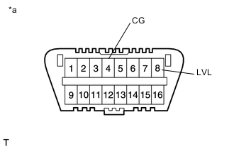
Text in Illustration *a Front view of DLC3 Connect terminals 4 (CG) and 8 (LVL) of the DLC3 using SST.
-
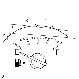
Turn the low beam headlights on and off using the light control switch within 20 seconds after connecting the terminals.
Tech Tips
The number of times the low beam headlights need to be turned on and off is determined by the present fuel level as shown below.
Fuel Level Number of Times to Turn Low Beam Headlights on and off Fuel level is within range A. 1 Fuel level is within range B. 2 Fuel level is within range C. 3 Fuel level is within range D. 4 Fuel level is within range E. 5 Note
-
Turn the low beam headlights on and off at approximately 3-second intervals.
-
Be sure to operate the headlight dimmer switch from the outside of the vehicle.
-
-
Check the warning light.
OK Condition Specified Condition The headlight leveling ECU*1 or headlight swivel ECU*2 is replaced with a new one. Blinks 6 times at 2 Hz → Blinks N* times at 2 Hz, and then turns off. Removal and reinstallation of the headlight leveling ECU*1 or headlight swivel ECU*2, replacement of the rear height control sensor LH, removal and reinstallation of the rear height control sensor LH, replacement of the suspension, etc. Off → Blinks N* times at 2 Hz, and then turns off. *1: w/ Static Headlight Auto Leveling
*2: w/ Dynamic Headlight Auto Leveling
Tech Tips
-
*: The number of times that the indicator blinks is determined by the number of times the low beam headlights are turned on and off.
-
If the calculated vehicle height is not within the acceptable range, the rear height control sensor initialization will end as an abnormal termination, and the warning indicator will blink 6 times at 2 Hz continuously. Disconnect SST from the DLC3 and turn the ignition switch off. Then restart from "Check Warning Light".
-
If initialization cannot be finished normally, perform inspections and repairs according to "Problem Symptoms Table".
Result Result Proceed to OK END NG See procedure LIGHTING (EXT) / LIGHTING SYSTEM / HOW TO PROCEED WITH TROUBLESHOOTING -
-
-
-
ADJUSTMENT FOR HEADLIGHT ASSEMBLY (for Halogen Headlight)
Tech Tips
It is possible that a bulb is incorrectly installed, affecting headlight aim. Bulb installation should be considered prior to performing the adjustment procedure.
-
VEHICLE PREPARATION FOR HEADLIGHT AIMING ADJUSTMENT
-
Prepare the vehicle:
-
Make sure that there is no damage to the body around the headlights.
-
Fill the fuel tank.
-
Make sure that the oil is filled to the specified level.
-
Make sure that the coolant is filled to the specified level.
-
Inflate the tires to the appropriate pressure.
-
Unload the trunk and vehicle, ensuring that the spare tire, tools and jack are in their original positions.
-
Have a person of average weight (75 kg, 165 lb) sit in the driver seat.
-
Vehicles with height adjustable suspension should have the vehicle height set to the lowest setting prior to adjusting the headlight aim.
-
Vehicles with manually adjustable headlights should be adjusted to "0" (w/ headlight leveling switch).
-
-
-
PREPARATION FOR HEADLIGHT AIMING (Using a screen)
-
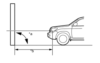
Text in Illustration *a 90° *b 25 m or 3 m Prepare the vehicle:
-
Place the vehicle in a location that is dark enough to clearly observe the cutoff line. The cutoff line is a distinct line, below which light from the headlights can be observed and above which it cannot.
-
Place the vehicle at a 90° angle to the wall.
-
Create a 25 m (82 ft.) distance between the vehicle (headlight bulb center) and the wall.
-
Make sure that the vehicle is on a level surface.
-
Bounce the vehicle up and down to settle the suspension.
Note
A distance of 25 m (82 ft.) between the vehicle (headlight bulb center) and the wall is necessary for proper aim adjustment. If unavailable, secure a distance of exactly 3 m (9.84 ft.) for the check and adjustment. (The target zone will change with the distance, so follow the instructions in the illustration).
-
-
Prepare a piece of thick white paper approximately 2 m (6.56 ft.) (height) x 4 m (13.1 ft.) (width) to use as a screen.
-
Draw a vertical line down the center of the screen (V line).
-
Set the screen as shown in the illustration.
Tech Tips
-
Stand the screen perpendicular to the ground.
-
Align the V line on the screen with the center of the vehicle.
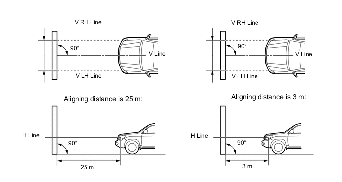
-
-
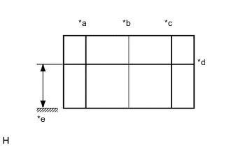
Text in Illustration *a V LH Line *b V Line *c V RH Line *d H Line *e Ground Draw base lines (H, V LH, and V RH lines) on the screen as shown in the illustration.
Tech Tips
-
The base lines differ for "low beam inspection" and "high beam inspection".
-
Mark the headlight bulb center marks on the screen. If the center mark cannot be observed on the headlight, use the center of the headlight bulb or the name of the manufacturer marked on the headlight as the center mark.
-
H Line (Headlight height):
Draw a horizontal line across the screen so that it passes through the center marks. The H line should be at the same height as the headlight bulb center marks of the low beam headlights.
-
V LH Line, V RH Line (Center mark position of the left-hand (LH) and right-hand (RH) headlights):
Draw 2 vertical lines so that they intersect the H line at each center mark (aligned with the center of the low beam headlight bulbs).
-
-
-
INSPECT HEADLIGHT AIMING
-
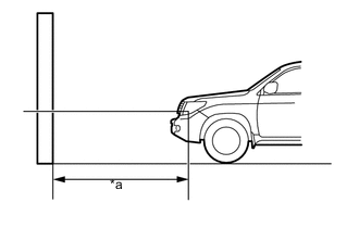
Text in Illustration *a 25 m or 3 m (82 ft. or 9.84 ft.) Cover the headlight or disconnect the connector of the headlight on the opposite side to prevent light from the headlight that is not being inspected from affecting the headlight aiming.
Note
Do not keep the headlight covered for more than 3 minutes. The headlight lens is made of synthetic resin, which may melt or be damaged due to excessive heat.
Tech Tips
When checking the aim of the high beam headlight, cover the low beam headlight or disconnect the connector.
-
Start the engine.
-
Turn on the headlight and check if the cutoff line matches the preferred cutoff line in the following illustration.
Tech Tips
-
Since the low beam and high beam headlight on each side have separate reflectors, it is necessary to check and adjust the aim separately for both.
-
The illustration is for LHD vehicles. RHD vehicles are the opposite of the illustration.
-
If the alignment distance is 25 m (82 ft.):
The low beam cutoff line should be within 83 mm (3.27 in.) and 375 mm (14.8 in.) below the H line as well as 249 mm (9.80 in.) left or right of the V LH or V RH line.
-
If the alignment distance is 3 m (9.84 ft.):
The low beam cutoff line should be within 10 mm (0.394 in.) and 45 mm (1.77 in.) below the H line as well as 30 mm (1.18 in.) left or right of the V LH or V RH line.
-
If the alignment distance is 25 m (82 ft.):
The horizontal line of the preferred low beam cutoff line is 249 mm (9.80 in.) below the H line and point A of the preferred low beam cutoff line is on the V LH or V RH line.
-
If the alignment distance is 3 m (9.84 ft.):
The horizontal line of the preferred low beam cutoff line is 30 mm (1.18 in.) below the H line and point A of the preferred low beam cutoff line is on the V LH or V RH line.
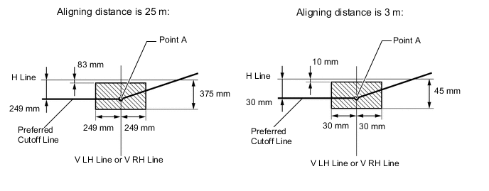
-
-
Turn on the high beams and check if the center of intensity for each high beam matches the center of intensity in the illustration.
Tech Tips
-
Since the low beam light and the high beam light on each side have separate reflectors, it is necessary to check and adjust the aim separately for both.
-
If the alignment distance is 25 m (82.0 ft.):
The high beam center of intensity should be within 175 mm (6.88 in.) above and 249 mm (9.80 in.) below the H line as well as 497 mm (1.63 ft.) left or right of the V LH or V RH line.
-
If the alignment distance is 3 m (9.84 ft.):
The high beam center of intensity should be within 21 mm (0.82 in.) above and 30 mm (1.18 in.) below the H line as well as 60 mm (2.36 in.) left or right of the V LH or V RH line.
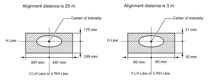
-
-
-
ADJUSTMENT HEADLIGHT AIMING
-
Headlight low beam.
-
Using a screwdriver, adjust the aim.
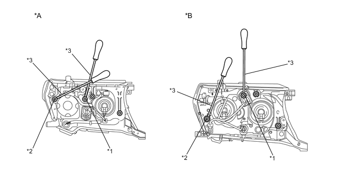
Text in Illustration *A w/ Projector *B w/o Projector *1 Vertical Aiming Screw *2 Horizontal Aiming Screw *3 Screwdriver - - Adjust the aim of each headlight to the specified range by turning each aiming screw with a screwdriver.
Note
The final turn of the aiming screw should be made in the clockwise direction. If the screw is tightened excessively, loosen it and then retighten it, so that the final turn of the screw is in the clockwise direction.
Tech Tips
-
Since the low beam light and the high beam light on each side have separate reflectors, it is necessary to check and adjust the aim separately for both.
-
When adjusting the horizontal axis of the headlight, the vertical axis will also change. It is necessary to adjust the horizontal position first, and then correct the vertical position.
-
If it is not possible to correctly adjust headlight aim, check the bulb, headlight unit and headlight unit reflector installation.
-
The headlight aim moves up when turning the vertical aiming screw clockwise, and moves down when turning the vertical aiming screw counterclockwise. The headlight aim moves right when turning the horizontal aiming screw clockwise, and moves left when turning the horizontal aiming screw counterclockwise.
-
Confirm the direction of rotation of the aiming screw by observing it while it is being adjusted. Due to the position of the screwdriver, the direction of rotation of the adjusting screw can be different than the direction of rotation of the screwdriver being used to adjust it.
-
-
-
Headlight high beam.
-
Using a screwdriver, adjust the aim.
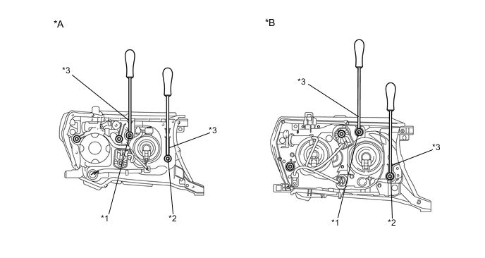
Text in Illustration *A w/ Projector *B w/o Projector *1 Vertical Aiming Screw *2 Horizontal Aiming Screw *3 Screwdriver - - Adjust the aim of each headlight so that it is within the specified range by turning each aiming screw with a screwdriver.
Note
The final turn of the aiming screw should be made in the clockwise direction. If the screw is tightened excessively, loosen it and then retighten it, so that the final turn of the screw is in the clockwise direction.
Tech Tips
-
Since the low beam light and the high beam light on each side have separate reflectors, it is necessary to check and adjust the aim separately for both.
-
When adjusting the horizontal axis of the headlight, the vertical axis will also change. It is necessary to adjust the horizontal position first, and then correct the vertical position.
-
If it is not possible to correctly adjust headlight aim, check the bulb, headlight unit and headlight unit reflector installation.
-
The headlight aim moves up when turning the vertical aiming screw clockwise, and moves down when turning the vertical aiming screw counterclockwise. The headlight aim moves right when turning the horizontal aiming screw clockwise, and moves left when turning the horizontal aiming screw counterclockwise.
-
Confirm the direction of rotation of the aiming screw by observing it while it is being adjusted. Due to the position of the screwdriver, the direction of rotation of the adjusting screw can be different than the direction of rotation of the screwdriver being used to adjust it.
-
-
-
-
-
ADJUSTMENT FOR HEADLIGHT ASSEMBLY (for HID Headlight)
Tech Tips
-
Use the same procedure for the RH and LH sides.
-
The procedure listed below is for the LH side.
-
It is possible that a bulb is incorrectly installed, affecting headlight aim. Bulb installation should be considered prior to performing the adjustment procedure.
-
VEHICLE PREPARATION FOR HEADLIGHT AIMING ADJUSTMENT
-
Prepare the vehicle:
-
Make sure that there is no damage to the body around the headlights.
-
Fill the fuel tank.
-
Make sure that the oil is filled to the specified level.
-
Make sure that the coolant is filled to the specified level.
-
Inflate the tires to the appropriate pressure.
-
Unload the trunk and vehicle, ensuring that the spare tire, tools and jack are in their original positions.
-
Have a person of average weight (75 kg, 165 lb) sit in the driver seat.
-
Vehicles with height adjustable suspension should have the vehicle height set to the lowest setting prior to adjusting the headlight aim (w/ Active Height Control).
-
-
-
Text in Illustration *a 90° *b 25 m or 3 m PREPARATION FOR HEADLIGHT AIMING (Using a screen)
-
except China:
Prepare the vehicle.
-
Place the vehicle in a location that is dark enough to clearly observe the cutoff line. The cutoff line is a distinct line, below which light from the headlights can be observed and above which it cannot.
-
Place the vehicle at a 90° angle to the wall.
-
Create a 25 m (82 ft.) distance between the vehicle (headlight bulb center) and the wall.
-
Make sure that the vehicle is on a level surface.
-
Bounce the vehicle up and down to settle the suspension.
Note
A distance of 25 m (82 ft.) between the vehicle (headlight bulb center) and the wall is necessary for proper aim adjustment. If unavailable, secure a distance of exactly 3 m (9.84 ft.) for the check and adjustment. (The target zone will change with the distance, so follow the instructions in the illustration).
-
-
Text in Illustration *a 90° *b 10 m or 3 m for China:
Prepare the vehicle.
-
Place the vehicle in a location that is dark enough to clearly observe the cutoff line. The cutoff line is a distinct line, below which light from the headlights can be observed and above which it cannot.
-
Place the vehicle at a 90° angle to the wall.
-
Create a 10 m (32.8 ft) distance between the vehicle (fog light bulb center) and the wall.
-
Make sure that the vehicle is on a level surface.
-
Bounce the vehicle up and down to settle the suspension.
Note
A distance of 10 m (32.8 ft.) between the vehicle (headlight bulb center) and the wall is necessary for proper aim adjustment. If unavailable, secure a distance of exactly 3 m (9.84 ft.) for the check and adjustment. (The target zone will change with the distance, so follow the instructions in the illustration).
-
-
Prepare a piece of thick white paper approximately 2 m (6.56 ft.) (height) x 4 m (13.1 ft.) (width) to use as a screen.
-
Draw a vertical line down the center of the screen (V line).
-
except China:
Set the screen as shown in the illustration.
Tech Tips
-
Stand the screen perpendicular to the ground.
-
Align the V line on the screen with the center of the vehicle.
-
-
for China:
Set the screen as shown in the illustration.
Tech Tips
-
Stand the screen perpendicular to the ground.
-
Align the V line on the screen with the center of the vehicle.
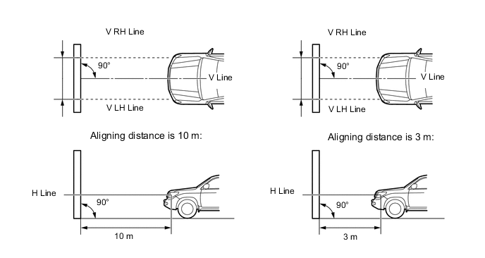
-
-
Text in Illustration *a V LH Line *b V Line *c V RH Line *d H Line *e Ground Draw base lines (H, V LH, and V RH lines) on the screen as shown in the illustration.
Tech Tips
-
The base lines differ for "low beam inspection" and "high beam inspection".
-
Mark the headlight bulb center marks on the screen. If the center mark cannot be observed on the headlight, use the center of the headlight bulb or the name of the manufacturer marked on the headlight as the center mark.
-
H Line (Headlight height):
Draw a horizontal line across the screen so that it passes through the center marks. The H line should be at the same height as the headlight bulb center marks of the low beam headlights.
-
V LH Line, V RH Line (Center mark position of the left-hand (LH) and right-hand (RH) headlights):
Draw 2 vertical lines so that they intersect the H line at each center mark (aligned with the center of the low beam headlight bulbs).
-
-
-
INSPECT HEADLIGHT AIMING
-
Cover the headlight on the opposite side to prevent light from the headlight that is not being inspected from affecting the headlight aiming inspection.
CAUTION:
Do not disconnect the HID high voltage connector for the bulb when performing this aiming inspection.
Note
Do not keep the headlight covered for more than 3 minutes. The headlight lens is made of synthetic resin, which may melt or be damaged due to excessive heat.
Tech Tips
When checking the aim of the high beam headlight, cover the low beam headlight.
-
Start the engine.
-
except China:
Turn on the headlight and check if the cutoff line matches the preferred cutoff line in the following illustration.
Tech Tips
-
Since the low beam light and the high beam light on each side have separate reflectors, it is necessary to check and adjust the aim separately for both.
-
The illustration is for LHD vehicles. RHD vehicles are the opposite of the illustration.
-
If the alignment distance is 25 m (82 ft.):
The low beam cutoff line should be within 83 mm (3.27 in.) and 375 mm (1.47 in.) below the H line as well as 249 mm (9.80 in.) left or right of the V LH or V RH line.
-
If the alignment distance is 3 m (9.84 ft.):
The low beam cutoff line should be within 10 mm (0.394 in.) and 45 mm (1.77 in.) below the H line as well as 30 mm (1.18 in.) left or right of the V LH or V RH line.
-
If the alignment distance is 25 m (82 ft.):
The horizontal line of the preferred low beam cutoff line is 249 mm (9.80 in.) below the H line and point A of the preferred low beam cutoff line is on the V LH or V RH line.
-
If the alignment distance is 3 m (9.84 ft.):
The horizontal line of the preferred low beam cutoff line is 30 mm (1.18 in.) below the H line and point A of the preferred low beam cutoff line is on the V LH or V RH line.
-
-
for China:
Turn on the headlight and check if the cutoff line matches the preferred cutoff line in the following illustration.
Tech Tips
-
Since the low beam light and the high beam light on each side have separate reflectors, it is necessary to check and adjust the aim separately for both.
-
If the alignment distance is 10 m (32.8 ft.):
The low beam cutoff line should be within 147 mm (5.79 in.) and 241 mm (9.49 in.) below the H line as well as 99 mm (3.89 in.) left or right of the V LH or V RH line.
-
If the alignment distance is 3 m (9.84 ft.):
The low beam cutoff line should be within 44 mm (1.73 in.) and 72 mm (2.83 in.) below the H line as well as 30 mm (1.18 in.) left or right of the V LH or V RH line.
-
If the alignment distance is 10 m (32.8 ft.):
The horizontal line of the preferred low beam cutoff line is 189 mm (7.44 in.) below the H line and point A of the preferred low beam cutoff line is on the V LH or V RH line.
-
If the alignment distance is 3 m (9.84 ft.):
The horizontal line of the preferred low beam cutoff line is 57 mm (2.24 in.) below the H line and point A of the preferred low beam cutoff line is on the V LH or V RH line.
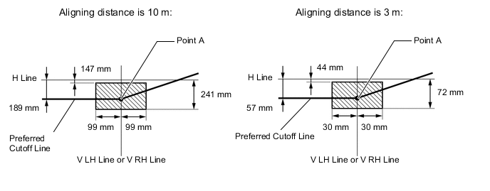
-
-
except China:
Turn on the high beams and check if the center of intensity for each high beam matches the center of intensity in the illustration.
Tech Tips
-
Since the low beam light and the high beam light on each side have separate reflectors, it is necessary to check and adjust the aim separately for both.
-
If the alignment distance is 25 m (82.0 ft.):
The high beam center of intensity should be within 175 mm (6.88 in.) above and 249 mm (9.80 in.) below the H line as well as 497 mm (1.63 ft.) left or right of the V LH or V RH line.
-
If the alignment distance is 3 m (9.84 ft.):
The high beam center of intensity should be within 21 mm (0.827 in.) above and 30 mm (1.18 in.) below the H line as well as 60 mm (2.36 in.) left or right of the V LH or V RH line.
-
-
for China:
Turn on the high beams and check if the center of intensity for each high beam matches the center of intensity in the illustration.
Tech Tips
-
Since the low beam light and the high beam light on each side have separate reflectors, it is necessary to check and adjust the aim separately for both.
-
If the alignment distance is 10 m (32.8 ft.):
The high beam center of intensity should be within 47 mm (1.85 in.) below the H line.
-
If the alignment distance is 3 m (9.84 ft.):
The high beam center of intensity should be within 14 mm (0.55 in.) below the H line.
-
If the alignment distance is 10 m (32.8 ft.):
The high beam center of intensity for the headlight assembly LH should be within 169 mm (6.65 in.) left and 349 mm (1.14 ft.) right of the V LH line.
-
If the alignment distance is 3 m (9.84 ft.):
The high beam center of intensity for the headlight assembly LH should be within 51 mm (2.0 in.) left and 105 mm (4.13 in.) right of the V LH line.
-
If the alignment distance is 10 m (32.8 ft.):
The high beam center of intensity for the headlight assembly RH should be within 349 mm (1.14 ft.) left or right of the V RH line.
-
If the alignment distance is 3 m (9.84 ft.):
The high beam center of intensity for the headlight assembly RH should be within 105 mm (4.13 in.) left or right of the V RH line.
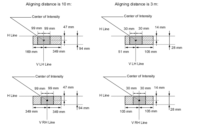
-
-
-
ADJUSTMENT HEADLIGHT AIMING
-
Headlight low beam.
-
Using a screwdriver, adjust the aim.
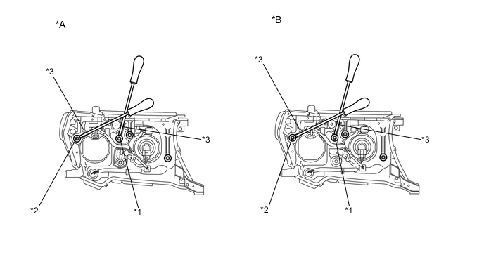
Text in Illustration *A Type 1 *B Type 2 *1 Vertical Aiming Screw *2 Horizontal Aiming Screw *3 Screwdriver - - Adjust the aim of each headlight so that it is within the specified range by turning each aiming screw with a screwdriver.
Note
The final turn of the aiming screw should be made in the clockwise direction. If the screw is tightened excessively, loosen it and then retighten it, so that the final turn of the screw is in the clockwise direction.
Tech Tips
-
Since the low beam light and the high beam light on each side have separate reflectors, it is necessary to check and adjust the aim separately for both.
-
When adjusting the horizontal axis of the headlight, the vertical axis will also change. It is necessary to adjust the horizontal position first, and then correct the vertical position.
-
If it is not possible to correctly adjust headlight aim, check the bulb, headlight unit and headlight unit reflector installation.
-
The headlight aim moves up when turning the vertical aiming screw clockwise, and moves down when turning the vertical aiming screw counterclockwise. The headlight aim moves right when turning the horizontal aiming screw clockwise, and moves left when turning the horizontal aiming screw counterclockwise.
-
Confirm the direction of rotation of the aiming screw by observing it while it is being adjusted. Due to the position of the screwdriver, the direction of rotation of the adjusting screw can be different than the direction of rotation of the screwdriver being used to adjust it.
-
-
-
Headlight high beam.
-
Using a screwdriver, adjust the aim.
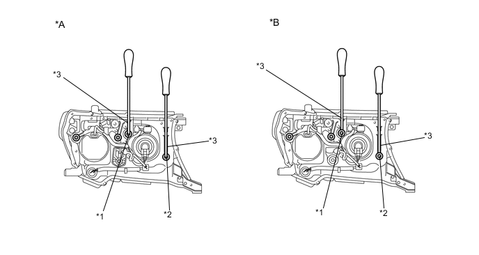
Text in Illustration *A Type 1 *B Type 2 *1 Vertical Aiming Screw *2 Horizontal Aiming Screw *3 Screwdriver - - Adjust the aim of each headlight so that it is within the specified range by turning each aiming screw with a screwdriver.
Note
The final turn of the aiming screw should be made in the clockwise direction. If the screw is tightened excessively, loosen it and then retighten it, so that the final turn of the screw is in the clockwise direction.
Tech Tips
-
Since the low beam light and the high beam light on each side have separate reflectors, it is necessary to check and adjust the aim separately for both.
-
When adjusting the horizontal axis of the headlight, the vertical axis will also change. It is necessary to adjust the horizontal position first, and then correct the vertical position.
-
If it is not possible to correctly adjust headlight aim, check the bulb, headlight unit and headlight unit reflector installation.
-
The headlight aim moves up when turning the vertical aiming screw clockwise, and moves down when turning the vertical aiming screw counterclockwise. The headlight aim moves right when turning the horizontal aiming screw clockwise, and moves left when turning the horizontal aiming screw counterclockwise.
-
Confirm the direction of rotation of the aiming screw by observing it while it is being adjusted. Due to the position of the screwdriver, the direction of rotation of the adjusting screw can be different than the direction of rotation of the screwdriver being used to adjust it.
-
-
-
-
-
ADJUSTMENT FOR HEADLIGHT ASSEMBLY (for LED Headlight)
Tech Tips
-
Use the same procedure for the RH and LH sides.
-
The procedure listed below is for the LH side.
-
VEHICLE PREPARATION FOR HEADLIGHT AIMING ADJUSTMENT
-
Prepare the vehicle:
Tech Tips
-
Make sure that there is no damage to the body around the headlights.
-
Fill the fuel tank.
-
Make sure that the oil is filled to the specified level.
-
Make sure that the coolant is filled to the specified level.
-
Inflate the tires to the appropriate pressure.
-
Unload the trunk and vehicle, ensuring that the spare tire, tools and jack are in their original positions.
-
Have a person of average weight (75 kg, 165 lb) sit in the driver seat.
-
Vehicles with manually adjustable headlights should be adjusted to "0" (w/ Headlight Leveling Switch).
-
-
-
Text in Illustration *a 90° *b 25 m or 3 m PREPARATION FOR HEADLIGHT AIMING (Using a screen)
-
Prepare the vehicle.
-
Place the vehicle in a location that is dark enough to clearly observe the cutoff line. The cutoff line is a distinct line, below which light from the headlights can be observed and above which it cannot.
-
Place the vehicle at a 90° angle to the wall.
-
Create a 25 m (82 ft.) distance between the vehicle (headlight bulb center) and the wall.
-
Make sure that the vehicle is on a level surface.
-
Bounce the vehicle up and down to settle the suspension.
Note
A distance of 25 m (82 ft.) between the vehicle (headlight bulb center) and the wall is necessary for proper aim adjustment. If unavailable, secure a distance of exactly 3 m (9.84 ft.) for the check and adjustment. (The target zone will change with the distance, so follow the instructions in the illustration).
-
-
Prepare a piece of thick white paper approximately 2 m (6.56 ft.) (height) x 4 m (13.1 ft.) (width) to use as a screen.
-
Draw a vertical line down the center of the screen (V line).
-
Set the screen as shown in the illustration.
Tech Tips
-
Stand the screen perpendicular to the ground.
-
Align the V line on the screen with the center of the vehicle.
-
-
Text in Illustration *a V LH Line *b V Line *c V RH Line *d H Line *e Ground Draw base lines (H, V LH, and V RH lines) on the screen as shown in the illustration.
Tech Tips
-
The base lines differ for "low beam inspection" and "high beam inspection".
-
Mark the headlight bulb center marks on the screen. If the center mark cannot be observed on the headlight, use the center of the headlight bulb or the name of the manufacturer marked on the headlight as the center mark.
-
H Line (Headlight height):
Draw a horizontal line across the screen so that it passes through the center marks. The H line should be at the same height as the headlight bulb center marks of the low beam headlights.
-
V LH Line, V RH Line (Center mark position of the left-hand (LH) and right-hand (RH) headlights):
Draw 2 vertical lines so that they intersect the H line at each center mark (aligned with the center of the low beam headlight bulbs).
-
-
-
INSPECT HEADLIGHT AIMING
-
Cover the headlight to prevent light from the headlight that is not being inspected from affecting the headlight aiming.
Note
Do not keep the headlight covered for more than 3 minutes. The headlight lens is made of synthetic resin, which may melt or be damaged due to excessive heat.
Tech Tips
When checking the aim of the high beam headlight, cover the low beam headlight.
-
Start the engine.
-
Turn on the headlight and check if the cutoff line matches the preferred cutoff line in the following illustration.
Tech Tips
-
Since the low beam and high beam headlight on each side have separate reflectors, it is necessary to check and adjust the aim separately for both.
-
If the alignment distance is 25 m (82 ft.):
The low beam cutoff line should be within 83 mm (3.27 in.) and 375 mm (14.8 in.) below the H line as well as 249 mm (9.80 in.) left or right of the V LH or V RH line.
-
If the alignment distance is 3 m (9.84 ft.):
The low beam cutoff line should be within 10 mm (0.394 in.) and 45 mm (1.77 in.) below the H line as well as 30 mm (1.18 in.) left or right of the V LH or V RH line.
-
If the alignment distance is 25 m (82 ft.):
The horizontal line of the preferred low beam cutoff line is 249 mm (9.80 in.) below the H line and point A of the preferred low beam cutoff line is on the V LH or V RH line.
-
If the alignment distance is 3 m (9.84 ft.):
The horizontal line of the preferred low beam cutoff line is 30 mm (1.18 in.) below the H line and point A of the preferred low beam cutoff line is on the V LH or V RH line.
-
-
Turn on the high beams and check if the center of intensity for each high beam matches the center of intensity in the illustration.
Tech Tips
-
Since the low beam light and the high beam light on each side have separate reflectors, it is necessary to check and adjust the aim separately for both.
-
If the alignment distance is 25 m (82 ft.):
The high beam center of intensity should be within 175 mm (6.88 in.) above and 249 mm (9.80 in.) below the H line as well as 497 mm (1.63 ft.) left or right of the V LH or V RH line.
-
If the alignment distance is 3 m (9.84 ft.):
The high beam center of intensity should be within 21 mm (0.82 in.) above and 30 mm (1.18 in.) below the H line as well as 60 mm (2.36 in.) left or right of the V LH or V RH line.
-
-
-
ADJUSTMENT HEADLIGHT AIMING
-
Headlight low beam.
-
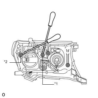
Text in Illustration *1 Vertical Aiming Screw *2 Horizontal Aiming Screw Using a screwdriver, adjust the aim.
Adjust the aim of each headlight so that it is within the specified range by turning each aiming screw with a screwdriver.
Note
The final turn of the aiming screw should be made in the clockwise direction. If the screw is tightened excessively, loosen it and then retighten it, so that the final turn of the screw is in the clockwise direction.
-
-
Headlight high beam.
-
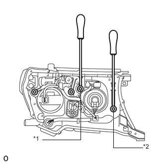
Text in Illustration *1 Vertical Aiming Screw *2 Horizontal Aiming Screw Using a screwdriver, adjust the aim.
Adjust the aim of each headlight so that it is within the specified range by turning each aiming screw with a screwdriver.
Note
The final turn of the aiming screw should be made in the clockwise direction. If the screw is tightened excessively, loosen it and then retighten it, so that the final turn of the screw is in the clockwise direction.
Tech Tips
-
Since the low beam light and the high beam light on each side have separate reflectors, it is necessary to check and adjust the aim separately for both.
-
When adjusting the horizontal axis of the headlight, the vertical axis will also change. It is necessary to adjust the horizontal position first, and then correct the vertical position.
-
If it is not possible to correctly adjust headlight aim, check the headlight assembly, No. 1 headlight bulb and reflector installation.
-
The headlight aim moves up when turning the vertical aiming screw clockwise, and moves down when turning the vertical aiming screw counterclockwise. The headlight aim moves right when turning the horizontal aiming screw clockwise, and moves left when turning the horizontal aiming screw counterclockwise.
-
Confirm the direction of rotation of the aiming screw by observing it while it is being adjusted. Due to the position of the screwdriver, the direction of rotation of the adjusting screw can be different than the direction of rotation of the screwdriver being used to adjust it.
-
-
-
-
-
ADJUSTMENT FOR FOG LIGHT ASSEMBLY
Tech Tips
-
Use the same procedure for the RH and LH sides.
-
The procedure listed below is for the LH side.
-
If there is a problem with the fog light aim, the cause of the problem may be an incorrectly installed bulb. Therefore, bulb installation should be checked prior to performing the adjustment procedure.
-
VEHICLE PREPARATION FOR FOG LIGHT AIMING ADJUSTMENT
-
Prepare the vehicle:
-
Make sure that there is no damage to or deformation of the body around the fog lights.
-
Fill the fuel tank.
-
Make sure that the oil is filled to the specified level.
-
Make sure that the coolant is filled to the specified level.
-
Inflate the tires to the appropriate pressure.
-
Unload the trunk and vehicle, ensuring that the spare tire, tools and jack are in their original positions.
-
Have a person of average weight (75 kg, 165 lb) sit in the driver's seat.
-
Vehicles with a height adjustable suspension should have the vehicle height set to the lowest setting prior to adjusting the fog light aim.
-
-
-
PREPARATION FOR FOG LIGHT AIMING
-
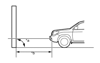
Text in Illustration *a 90° *b 25 m or 3 m except China:
Prepare the vehicle.
-
Place the vehicle in a location that is dark enough to clearly observe the cutoff line. The cutoff line is a distinct line, below which light from the fog lights can be observed and above which it cannot.
-
Place the vehicle at a 90° angle to the wall.
-
Create a 25 m (82 ft.) distance between the vehicle (fog light bulb center) and the wall.
-
Make sure that the vehicle is on a level surface.
-
Bounce the vehicle up and down to settle the suspension.
Note
A distance of 25 m (82 ft.) between the vehicle (fog light bulb center) and the wall is necessary for proper aim adjustment. If unavailable, secure a distance of exactly 3 m (9.84 ft.) for the check and adjustment. (The target zone will change with the distance, so follow the instructions in the illustration).
-
-
Text in Illustration *a 90° *b 10 m or 3 m for China:
Prepare the vehicle.
-
Place the vehicle in a location that is dark enough to clearly observe the cutoff line. The cutoff line is a distinct line, below which light from the fog lights can be observed and above which it cannot.
-
Place the vehicle at a 90° angle to the wall.
-
Create a 10 m (32.8 ft) distance between the vehicle (fog light bulb center) and the wall.
-
Make sure that the vehicle is on a level surface.
-
Bounce the vehicle up and down to settle the suspension.
Note
A distance of 10 m (32.8 ft) between the vehicle (fog light bulb center) and the wall is necessary for proper aim adjustment. If unavailable to secure a distance of exactly 3 m (9.84 ft) to check and adjustment. (The target zone will change with the distance, so follow the instructions in the illustration.)
-
-
Prepare a piece of thick white paper approximately 2.0 m (6.56 ft.) (height) x 4.0 m (13.1 ft.) (width) to use as a screen.
-
Draw a vertical line down the center of the screen (V line).
-
except China:
Set the screen as shown in the illustration.
Tech Tips
-
Stand the screen perpendicular to the ground.
-
Align the V line on the screen with the center of the vehicle.
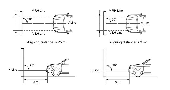
Tech Tips
-
Stand the screen perpendicular to the ground.
-
Align the V line on the screen with the center of the vehicle.
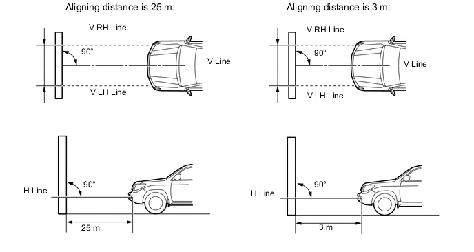
-
-
for China:
Set the screen as shown in the illustration.
Tech Tips
-
Stand the screen perpendicular to the ground.
-
Align the V line on the screen with the center of the vehicle.
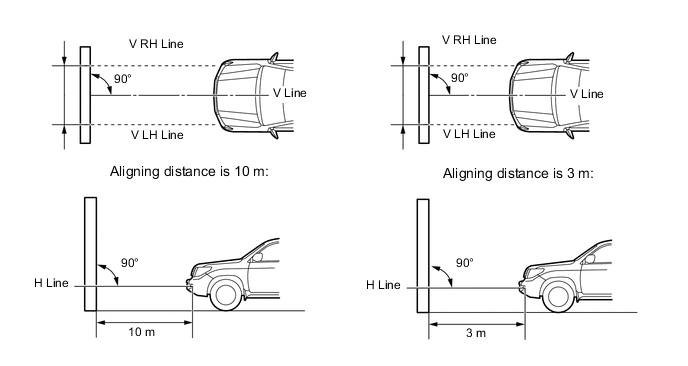
-
-
Text in Illustration *a V LH Line *b V Line *c V RH Line *d H Line *e Ground Draw base lines (H, V LH, and V RH lines) on the screen as shown in the illustration.
Tech Tips
Mark the fog light bulb center marks on the screen. If the center mark cannot be observed on the fog light, use the center of the fog light bulb or the manufacturer's name marked on the fog light as the center mark.
-
H line (Fog light height):
Draw a horizontal line across the screen so that it passes through the center marks. The H line should be at the same height as the fog light bulb center marks of the fog lights.
-
V LH Line, V RH Line (Center mark position of left-hand (LH) and right-hand (RH) fog lights):
Draw 2 vertical lines so that they intersect the H line at each center mark.
-
-
-
INSPECT FOG LIGHT AIMING
-
Cover the fog light or disconnect the connector of the fog light on the opposite side to prevent light from the fog light that is not being inspected from affecting the fog light aiming inspection.
Note
Do not keep the fog light covered for more than 3 minutes. The fog light lens is made of synthetic resin, which may melt or be damaged due to excessive heat.
-
Start the engine.
-
except China:
Turn on the fog lights and check if the upper edge of the hot zone for each fog light matches the upper edge as shown in the illustration.
Tech Tips
-
If the alignment distance is 25 m (82 ft.):
The upper edge of the hot zone for the fog light should be 375 mm (1.48 in.) below the H line.
-
If the alignment distance is 3 m (9.84 ft.):
The upper edge of the hot zone for the fog light should be 45 mm (1.77 in.) below the H line.
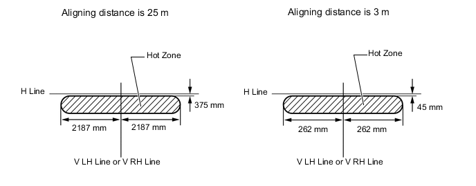
-
-
-
for China:
Turn on the fog lights and check if the upper edge of the hot zone for each fog light matches the upper edge as shown in the illustration.
Tech Tips
-
If the alignment distance is 10 m (32.8 ft.):
The upper edge of the hot zone for the fog light should be 150 mm (5.91 in.) below the H line.
-
If the alignment distance is 3 m (9.84 ft.):
The upper edge of the hot zone for the fog light should be 45 mm (1.77 in.) below the H line.
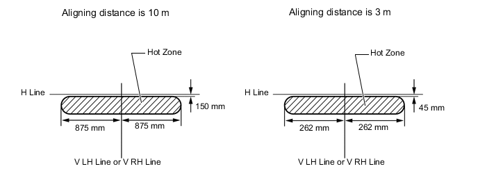
-
-
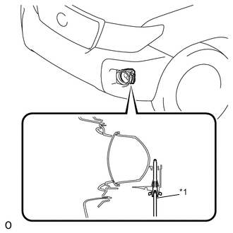
Text in Illustration *1 Aiming screw ADJUSTMENT FOG LIGHT AIMING
-
Adjust the aim vertically:
Adjust the aim of each fog light so that it is within the specified range by turning the aiming screw with a screwdriver.
Note
The final turn of the aiming screw should be made in the clockwise direction. If the screw is tightened excessively, loosen it and then retighten it, so that the final turn of the screw is in the clockwise direction.
Tech Tips
If it is not possible to correctly adjust fog light aim, check the bulb, fog light unit, and fog light unit reflector installation.
-
-