OIL PUMP INSPECTION

PROCEDURE
-
INSPECT OIL PUMP RELIEF VALVE
-
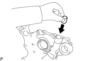
Coat the relief valve with engine oil.
-
Check that the relief valve falls smoothly into the valve hole by its own weight.
If the relief valve is not as specified, replace it. If necessary, replace the timing chain cover sub-assembly.
-
-
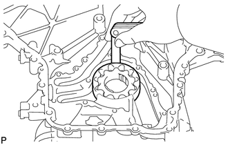
INSPECT OIL PUMP ROTOR SET
-
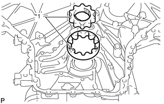
Text in Illustration *1 Mark Install the rotors to the timing chain cover with the marks on the rotors facing outward. Check that the rotors revolve smoothly.
If they do not rotate smoothly, replace the timing chain cover sub-assembly.
-
Check the tip clearance.
-
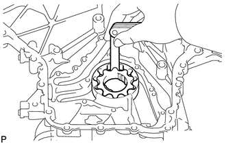
Using a feeler gauge, measure the clearance between the drive and driven rotor tips as shown in the illustration.
Standard tip clearance 0.180 to 0.300 mm (0.00709 to 0.0118 in.) Maximum tip clearance 0.300 mm (0.0118 in.) If the tip clearance is more than the maximum, replace the oil pump rotor set.
-
-
Check the side clearance.
-
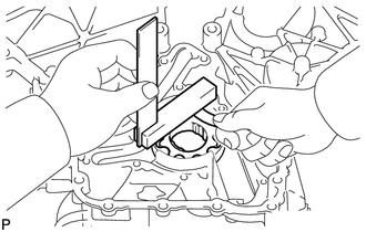
Using a feeler gauge and steel square, measure the clearance between the rotors and steel square as shown in the illustration.
Standard side clearance 0.030 to 0.090 mm (0.00118 to 0.00354 in.) Maximum side clearance 0.090 mm (0.00354 in.) If the side clearance is more than the maximum, replace the oil pump rotor set. If necessary, replace the timing chain cover sub-assembly.
-
-
Check the body clearance.
-
Using a feeler gauge, measure the clearance between the timing chain cover and driven rotor as shown in the illustration.
Standard body clearance 0.175 to 0.250 mm (0.00689 to 0.00984 in.) Maximum body clearance 0.250 mm (0.00984 in.) If the body clearance is more than the maximum, replace the oil pump rotor set. If necessary, replace the timing chain cover sub-assembly.
-
-