RADIATOR INSTALLATION
PROCEDURE
-
INSTALL RADIATOR ASSEMBLY
-
Install the radiator with the 4 bolts.
- Torque:
- 18 N*m { 184 kgf*cm, 13 ft.*lbf }
-
-
INSTALL FAN PULLEY
-
INSTALL FAN SHROUD WITH FAN
-
INSTALL OIL COOLER TUBE (for Automatic Transmission)
-
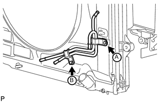
Temporarily install the oil cooler tube to the fan shroud with the bolt labeled A. Install the bolt labeled B. Then tighten the bolt labeled A to the specified torque.
- Torque:
- 5.0 N*m { 51 kgf*cm, 44 in.*lbf }
-
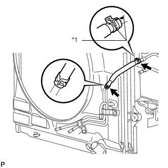
Text in Illustration *1 Paint Mark Connect the inlet No. 4 oil cooler hose as shown in the illustration.
Note
Make sure the pinching portion of each clip is facing the direction shown in the illustration.
-
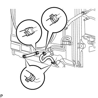
Connect the inlet No. 2 and No. 3 oil cooler hoses as shown in the illustration.
Note
Make sure the pinching portion of each clip is facing the direction shown in the illustration.
-
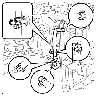
Text in Illustration *1 Paint Mark Connect the inlet and outlet No. 1 oil cooler hoses as shown in the illustration.
Note
Make sure the pinching portion of each clip is facing the direction shown in the illustration.
-
Pass the hose through the flexible hose clamp and close the clamp shown in the illustration.
-
-
INSTALL V-RIBBED BELT
-
INSTALL NO. 3 IDLER PULLEY (w/ Viscous Heater)
-
INSTALL NO. 1 IDLER PULLEY (w/ Viscous Heater)
-
INSTALL V-RIBBED BELT (w/ Viscous Heater)
-
CONNECT NO. 2 RADIATOR HOSE
-
CONNECT NO. 1 RADIATOR HOSE
-
INSTALL RADIATOR RESERVOIR ASSEMBLY
-
INSTALL NO. 1 OIL RESERVOIR BRACKET
-
INSTALL VANE PUMP OIL RESERVOIR ASSEMBLY
-
INSTALL INTAKE AIR CONNECTOR
-
TEMPORARILY INSTALL NO. 1 AIR CLEANER HOSE
-
INSTALL AIR CLEANER CAP SUB-ASSEMBLY
-
INSTALL NO. 1 ENGINE COVER SUB-ASSEMBLY (w/ Intercooler)
-
INSTALL NO. 3 ENGINE ROOM WIRE
-
CONNECT CABLE TO NEGATIVE BATTERY TERMINAL
Note
When disconnecting the cable, some systems need to be initialized after the cable is reconnected Click here.
-
Connect the cables to negative (-) main battery and sub-battery terminals.
-
-
ADD ENGINE COOLANT
-
INSPECT FOR ENGINE COOLANT LEAK
-
INSTALL RADIATOR SIDE DEFLECTOR LH
-
Install the side deflector with the 4 clips.
-
-
INSTALL RADIATOR SIDE DEFLECTOR RH (for Manual Transmission)
-
Install the deflector with the 4 clips.
-
-
INSTALL TRANSMISSION OIL COOLER AIR DUCT (for Automatic Transmission)
-
Install the oil cooler air duct with the 4 bolts.
- Torque:
- 4.9 N*m { 50 kgf*cm, 43 in.*lbf }
-
-
INSTALL FRONT BUMPER COVER
-
for Standard: Click here
-
w/ Winch: Click here
-
-
INSTALL RADIATOR GRILLE
-
INSTALL FRONT BUMPER WINCH COVER (w/ Winch)
-
INSTALL UPPER RADIATOR SUPPORT SEAL
-
INSTALL FRONT FENDER APRON SEAL FRONT RH
-
INSTALL FRONT WHEEL RH
-
INSTALL NO. 1 ENGINE UNDER COVER SUB-ASSEMBLY
-
INSTALL FRONT FENDER SPLASH SHIELD SUB-ASSEMBLY RH
-
INSTALL FRONT FENDER SPLASH SHIELD SUB-ASSEMBLY LH