THERMOSTAT INSTALLATION
PROCEDURE
-
INSTALL THERMOSTAT
-
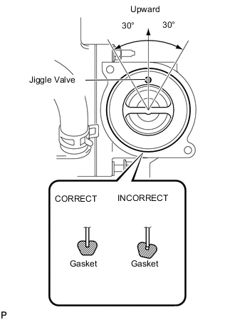
Install a new gasket to the thermostat.
Note
When installing the gasket to the thermostat, be careful not to deform the gasket. Make sure that the groove of the gasket is properly installed onto the thermostat, as shown in the illustration.
-
Insert the thermostat into the water pump with the jiggle valve facing straight upward.
Tech Tips
The jiggle valve may be set within 30° of either side of the prescribed position.
-
-
INSTALL WATER INLET
-
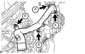
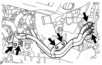
Install the water inlet with the 4 bolts.
- Torque:
- for bolt A
- 21 N*m { 214 kgf*cm, 15 ft.*lbf }
- for bolt B
- 25 N*m { 250 kgf*cm, 18 ft.*lbf }
-
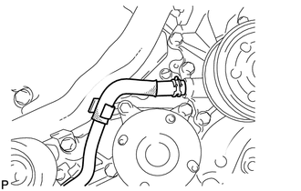
Connect the No. 2 oil cooler hose to the clamp and water pump.
-
-
INSTALL NO. 1 IDLER PULLEY BRACKET (w/ Viscous Heater)
-
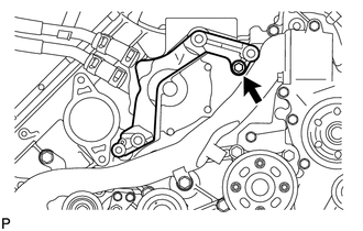
Install the No. 1 idler pulley bracket with the bolt.
- Torque:
- 49 N*m { 495 kgf*cm, 36 ft.*lbf }
-
-
INSTALL VISCOUS WITH MAGNET CLUTCH HEATER ASSEMBLY (w/ Viscous Heater)
-
INSTALL HEATER WATER PIPE SUB-ASSEMBLY (w/ Viscous Heater)
-
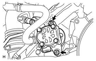
Connect the heater water pipe to the viscous heater with magnet clutch, and install the 4 bolts.
- Torque:
- 9.8 N*m { 100 kgf*cm, 87 in.*lbf }
-
-
INSTALL FAN PULLEY
-
INSTALL FAN SHROUD WITH FAN
-
Install the shroud together with the fluid coupling fan between the radiator and engine components.
Note
Be careful not to damage the radiator core.
-
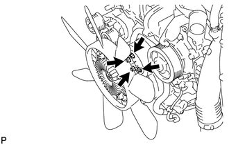
Temporarily install the fluid coupling fan to the fan bracket with the 4 nuts.
Tech Tips
Tighten the nuts as much as possible by hand.
-
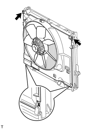
Attach the shroud claws to the radiator.
-
Install the shroud with the 2 bolts.
- Torque:
- 8.0 N*m { 82 kgf*cm, 71 in.*lbf }
-
Tighten the 4 nuts of the fluid coupling fan.
- Torque:
- 21 N*m { 214 kgf*cm, 15 ft.*lbf }
-
-
INSTALL OIL COOLER TUBE (for Automatic Transmission)
-
INSTALL V-RIBBED BELT
-
INSTALL NO. 3 IDLER PULLEY (w/ Viscous Heater)
-
INSTALL NO. 1 IDLER PULLEY (w/ Viscous Heater)
-
INSTALL V-RIBBED BELT (w/ Viscous Heater)
-
CONNECT NO. 2 RADIATOR HOSE
-
CONNECT NO. 1 RADIATOR HOSE
-
INSTALL VANE PUMP ASSEMBLY
-
Apply a light coat of engine oil to a new O-ring, and install it to the vane pump.
-
Install the vane pump with 2 new nuts.
- Torque:
- 29 N*m { 296 kgf*cm, 21 ft.*lbf }
-
-
INSTALL RADIATOR RESERVOIR ASSEMBLY
-
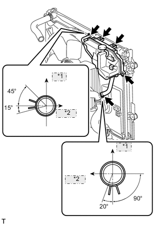
*1 Upper *2 RH Side Install the radiator reservoir with the 3 bolts.
-
Connect the 2 hoses to the upper radiator tank and water inlet.
Tech Tips
Make sure the directions of the hose clamps are as shown in the illustration.
-
-
INSTALL NO. 1 OIL RESERVOIR BRACKET
-
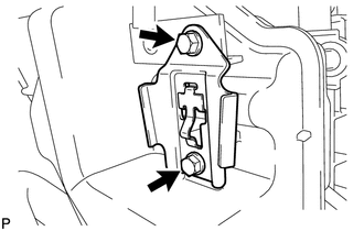
Install a new bracket with the 2 bolts.
- Torque:
- 4.5 N*m { 46 kgf*cm, 40 in.*lbf }
-
-
INSTALL VANE PUMP OIL RESERVOIR ASSEMBLY
-
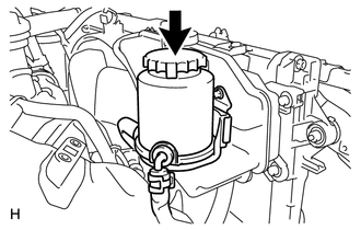
Install the vane pump oil reservoir to the bracket.
-
-
INSTALL INTAKE AIR CONNECTOR
-
TEMPORARILY INSTALL NO. 1 AIR CLEANER HOSE
-
INSTALL AIR CLEANER CAP SUB-ASSEMBLY
-
INSTALL NO. 1 ENGINE COVER SUB-ASSEMBLY (w/ Intercooler)
-
INSTALL NO. 3 ENGINE ROOM WIRE
-
Install the No. 3 engine room wire to the main battery and sub-battery positive terminals with the 2 nuts.
- Torque:
- 7.6 N*m { 77 kgf*cm, 67 in.*lbf }
-
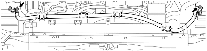
Connect the No. 3 engine room wire with the 4 clamps.
-
-
CONNECT CABLE TO NEGATIVE BATTERY TERMINAL
Note
When disconnecting the cable, some systems need to be initialized after the cable is reconnected Click here.
-
Connect the cables to negative (-) main battery and sub-battery terminals.
-
-
ADD ENGINE COOLANT
-
INSPECT FOR ENGINE COOLANT LEAK
-
INSTALL UPPER RADIATOR SUPPORT SEAL
-
INSTALL NO. 1 ENGINE UNDER COVER SUB-ASSEMBLY
-
INSTALL FRONT FENDER SPLASH SHIELD SUB-ASSEMBLY RH
-
INSTALL FRONT FENDER SPLASH SHIELD SUB-ASSEMBLY LH
-
INSTALL FRONT FENDER APRON SEAL FRONT RH
-
INSTALL FRONT WHEEL RH