INTERCOOLER INSTALLATION
PROCEDURE
-
INSTALL ENGINE COVER BRACKET
-
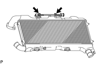
Install the engine cover bracket with the 2 bolts.
- Torque:
- 9.0 N*m { 92 kgf*cm, 80 in.*lbf }
-
-
INSTALL INTERCOOLER ASSEMBLY
-
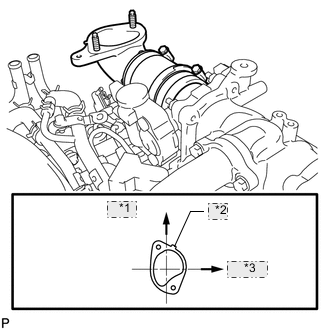
*1 Front *2 Protrusion *3 RH Side Install a new gasket to the air tube RH.
Tech Tips
Install the gasket with the protrusion facing as shown in the illustration.
-
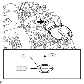
*1 Protrusion *2 Front *3 LH Side Install a new gasket to the air tube LH.
Tech Tips
Install the gasket with the protrusion facing as shown in the illustration.
-

Align the No. 1 and No. 2 air hoses and intercooler pipes and connect them, and install the intercooler with the 2 bolts and 2 nuts labeled A in the illustration.
- Torque:
- 21 N*m { 214 kgf*cm, 15 ft.*lbf }
-
Temporarily install the 4 nuts labeled B in the illustration.
-
Tighten the air tube LH and RH with the 4 nuts labeled B shown in the illustration.
- Torque:
- 21 N*m { 214 kgf*cm, 15 ft.*lbf }
-
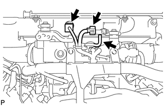
Connect the vacuum hose, intake air temperature sensor connector and turbo pressure sensor connector.
-
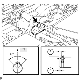
*1 Upper Tighten the clamp of the No. 2 air hose.
- Torque:
- 6.3 N*m { 64 kgf*cm, 56 in.*lbf }
Tech Tips
-
Align the paint mark of the air hose with the protrusion and push in the air hose so that distance B is 0 to 3 mm (0 to 0.118 in.).
-
Position the clamp so that distance A is 2 to 6 mm (0.0787 to 0.236 in.).
-
Make sure the direction of the hose clamp is as shown in the illustration.
-
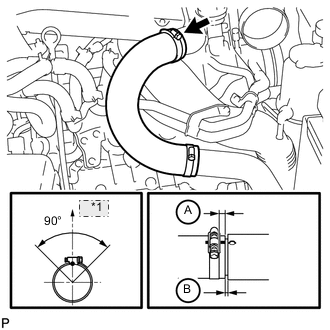
*1 Upper Tighten the clamp of the No. 1 air hose.
- Torque:
- 6.3 N*m { 64 kgf*cm, 56 in.*lbf }
Tech Tips
-
Align the paint mark of the air hose with the protrusion and push in the air hose so that distance B is 0 to 3 mm (0 to 0.118 in.).
-
Position the clamp so that distance A is 2 to 6 mm (0.0787 to 0.236 in.).
-
Make sure the direction of the hose clamp is as shown in the illustration.
-
-
INSTALL NO. 1 ENGINE COVER SUB-ASSEMBLY
-
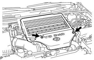
Install the engine cover with the 2 nuts.
- Torque:
- 8.0 N*m { 82 kgf*cm, 71 in.*lbf }
-
-
INSTALL COWL TOP VENTILATOR LOUVER SUB-ASSEMBLY
-
INSTALL HOOD TO COWL TOP SEAL
-
INSTALL FRONT FENDER MAIN SEAL LH
-
INSTALL FRONT FENDER MAIN SEAL RH
-
INSTALL FRONT WIPER ARM LH
-
INSTALL FRONT WIPER ARM RH
-
INSTALL UPPER RADIATOR SUPPORT SEAL