EXHAUST MANIFOLD W/ TURBOCHARGER INSTALLATION
CAUTION / NOTICE / HINT
Note
w/ DPF:
When fuel lines are disconnected, air may enter the fuel lines, leading to engine starting trouble. Therefore, perform forced regeneration and bleed the air from the fuel lines Click here.
PROCEDURE
-
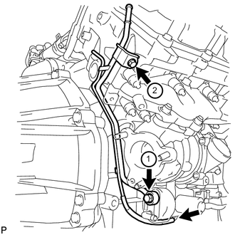
INSTALL NO. 2 INLET TURBO OIL PIPE SUB-ASSEMBLY (for Bank 2)
-
Temporarily install a new gasket and the No. 2 inlet turbo oil pipe with the union bolt and bolt.
-
Tighten the union bolt and bolt in the order shown in the illustration.
- Torque:
- for union bolt
- 29 N*m { 296 kgf*cm, 21 ft.*lbf }
- for bolt
- 10 N*m { 102 kgf*cm, 7 ft.*lbf }
-
-
INSTALL NO. 2 TURBO OIL PIPE (for Bank 2)
-
Install a new gasket and the No. 2 turbo oil pipe with the 2 bolts.
- Torque:
- 10 N*m { 102 kgf*cm, 7 ft.*lbf }
Tech Tips
The gasket claws should face the pipe.
-
-
INSTALL NO. 2 INLET COMPRESSOR ELBOW (for Bank 2)
-
Install a new gasket and the No. 2 inlet compressor elbow with the 2 bolts.
- Torque:
- 21 N*m { 214 kgf*cm, 15 ft.*lbf }
Tech Tips
Install the No. 2 inlet compressor elbow with the "L" mark facing toward the outside of the vehicle.
-
-
INSTALL NO. 2 TURBOCHARGER SUB-ASSEMBLY WITH EXHAUST MANIFOLD LH (for Bank 2)
-
Install a new gasket to the No. 2 turbocharger.
-
Install the exhaust manifold LH to the No. 2 turbocharger with 3 new nuts.
- Torque:
- 69 N*m { 704 kgf*cm, 51 ft.*lbf }
Tech Tips
The gasket claw should face toward the outside of the vehicle.
-
w/ DPF:
-
Install 2 new gaskets to the No. 2 exhaust manifold pipe.
Tech Tips
The gasket claws should face the No. 2 exhaust manifold pipe.
-
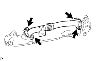
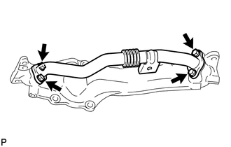
Temporarily install the No. 2 exhaust manifold pipe with the 4 bolts.
Tech Tips
Install the No. 2 exhaust manifold pipe so that it is oriented as shown in the illustration.
-
Tighten the 4 bolts.
- Torque:
- 21 N*m { 214 kgf*cm, 15 ft.*lbf }
-
-
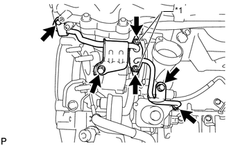
Install a new gasket to the cylinder head LH.
-
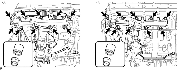
Install the No. 2 turbocharger with exhaust manifold LH and 10 collars to the cylinder head LH with 10 new nuts.
- Torque:
- 36 N*m { 367 kgf*cm, 27 ft.*lbf }
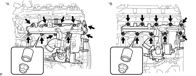
Text in Illustration *A w/ DPF *B w/o DPF Tech Tips
Install the collars with the colored side facing the nuts.
-
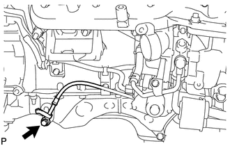
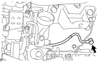
Install a new gasket and the No. 2 inlet turbo oil pipe to the No. 1 oil pan with the union bolt.
- Torque:
- 29 N*m { 296 kgf*cm, 21 ft.*lbf }
-
Connect the 2 connectors to the turbocharger.
-
-
INSTALL NO. 2 VENTILATION TUBE SUB-ASSEMBLY (for Bank 2)
-
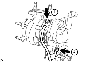
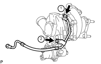
Temporarily install a new gasket and the No. 2 ventilation tube with the union bolt and bolt.
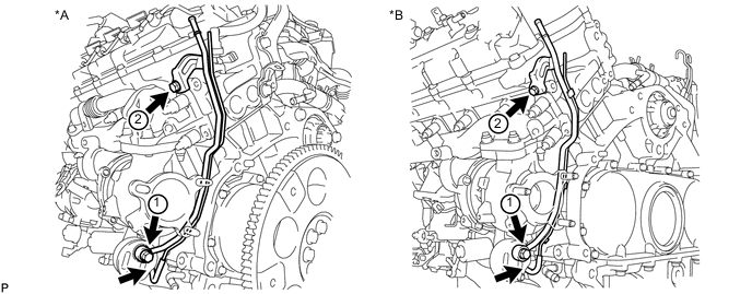
Text in Illustration *A w/ DPF *B w/o DPF -
Tighten the union bolt and bolt in the order shown in the illustration.
- Torque:
- for union bolt
- 29 N*m { 296 kgf*cm, 21 ft.*lbf }
- for bolt
- 10 N*m { 102 kgf*cm, 7 ft.*lbf }
Note
Clean and remove any oil in the area labeled 1 in the illustration.
-
Connect the hose.
-
-
INSTALL NO. 2 TURBOCHARGER STAY (for Bank 2)
-
Install the No. 2 turbocharger stay with the 2 bolts.
- Torque:
- 49 N*m { 495 kgf*cm, 36 ft.*lbf }
-
-
INSTALL NO. 2 OUTLET TURBO OIL HOSE (for Bank 2)
Tech Tips
Align the white paint marks on the oil hose and pipe, and connect the hose.
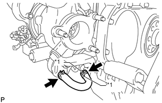
Text in Illustration *1 Painted Mark -
INSTALL NO. 2 TURBO WATER PIPE SUB-ASSEMBLY (for Bank 2)
-
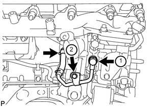
Temporarily install a new gasket and the No. 2 turbo water pipe with the union bolt and bolt.
-
Tighten the union bolt and bolt in the order shown in the illustration.
- Torque:
- for union bolt
- 35 N*m { 357 kgf*cm, 26 ft.*lbf }
- for bolt
- 10 N*m { 102 kgf*cm, 7 ft.*lbf }
-
Connect the water hose to the pipe.
-
-
INSTALL FRONT WATER BY-PASS JOINT (for Bank 2)
-
Install a new gasket and the front water by-pass joint.
- Torque:
- 50 N*m { 510 kgf*cm, 37 ft.*lbf }
-
-
INSTALL NO. 3 TURBO WATER PIPE SUB-ASSEMBLY (for Bank 2)
-
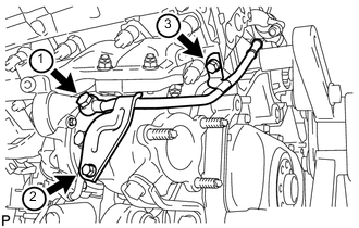
Temporarily install a new gasket and the No. 3 turbo water pipe with the union bolt and 2 bolts.
-
Tighten the union bolt and 2 bolts in the order shown in the illustration.
- Torque:
- for union bolt
- 35 N*m { 357 kgf*cm, 26 ft.*lbf }
- for bolt
- 10 N*m { 102 kgf*cm, 7 ft.*lbf }
-
-
INSTALL NO. 2 EXHAUST MANIFOLD HEAT INSULATOR (for Bank 2)
-
Install the No. 2 exhaust manifold heat insulator with the 3 bolts.
- Torque:
- 25 N*m { 255 kgf*cm, 18 ft.*lbf }
-
-
INSTALL NO. 2 TURBO WATER HOSE (for Bank 2)
-
INSTALL BREATHER PLUG LH (for Bank 2)
-
Install the breather plug LH.
-
w/o DPF:
Attach the clamp.
-
Connect the hose.
-
-
INSTALL NO. 3 VENTILATION HOSE (for Bank 2)
-
INSTALL NO. 1 INLET TURBO OIL PIPE SUB-ASSEMBLY (for Bank 1)
-
Temporarily install a new gasket and the No. 1 inlet turbo oil pipe with the union bolt and bolt.
-
Tighten the union bolt and bolt in the order shown in the illustration.
- Torque:
- for union bolt
- 29 N*m { 296 kgf*cm, 21 ft.*lbf }
- for bolt
- 10 N*m { 102 kgf*cm, 7 ft.*lbf }
-
-
INSTALL NO. 1 TURBO OIL PIPE (for Bank 1)
-
Install a new gasket and the No. 1 turbo oil pipe with the 2 bolts.
- Torque:
- 10 N*m { 102 kgf*cm, 7 ft.*lbf }
-
-
INSTALL NO. 1 INLET COMPRESSOR ELBOW (for Bank 1)
-
Install a new gasket and the No. 1 inlet compressor elbow with the 2 bolts.
- Torque:
- 21 N*m { 214 kgf*cm, 15 ft.*lbf }
Tech Tips
Install the No. 1 inlet compressor elbow with the "R" mark facing toward the outside of the vehicle.
-
-
INSTALL NO. 1 TURBOCHARGER SUB-ASSEMBLY WITH EXHAUST MANIFOLD RH (for Bank 1)
-
Install a new gasket to the No. 1 turbocharger.
-
Install the exhaust manifold RH to the No. 1 turbocharger with 2 new nuts and the bolt.
- Torque:
- 69 N*m { 704 kgf*cm, 51 ft.*lbf }
-
w/ DPF:
-
Install 2 new gaskets to the No. 1 exhaust manifold pipe.
Tech Tips
The gasket claws should face the No. 1 exhaust manifold pipe.
-
Temporarily install the No. 1 exhaust manifold pipe with the 4 bolts.
Tech Tips
Install the No. 1 exhaust manifold pipe so that it is oriented as shown in the illustration.
-
Tighten the 4 bolts.
- Torque:
- 21 N*m { 214 kgf*cm, 15 ft.*lbf }
-
-
Install a new gasket to the cylinder head RH.
-
Install the No. 1 turbocharger with exhaust manifold RH to the cylinder head RH with the 10 collars and 10 new nuts.
- Torque:
- 36 N*m { 367 kgf*cm, 27 ft.*lbf }
Text in Illustration *A w/ DPF *B w/o DPF Tech Tips
Install the collars with the colored side facing the nuts.
-
Install a new gasket and the No. 1 inlet turbo oil pipe to the cylinder block with the union bolt.
- Torque:
- When "dry"
- 29 N*m { 296 kgf*cm, 21 ft.*lbf }
- When "wet"
- 23 N*m { 235 kgf*cm, 17 ft.*lbf }
Note
-
The parts are "dry" when there is absolutely no engine oil on the union bolt and cylinder block bolt hole.
-
The parts are "wet" when there is engine oil on the union bolt and cylinder block bolt hole.
-
-
INSTALL NO. 1 VENTILATION TUBE SUB-ASSEMBLY (for Bank 1)
-
Temporarily install a new gasket and the No. 1 ventilation tube with the union bolt and bolt.
-
Tighten the union bolt and bolt in the order shown in the illustration.
- Torque:
- for union bolt
- 29 N*m { 296 kgf*cm, 21 ft.*lbf }
- for bolt
- 10 N*m { 102 kgf*cm, 7 in.*lbf }
Note
Clean and remove any oil in the area labeled 1 in the illustration.
-
Connect the hose.
-
-
INSTALL NO. 1 TURBOCHARGER STAY (for Bank 1)
-
Temporarily install the No. 1 turbocharger stay with the 2 bolts.
-
Tighten the 2 bolts.
- Torque:
- 49 N*m { 495 kgf*cm, 36 ft.*lbf }
-
-
INSTALL NO. 1 TURBO WATER PIPE SUB-ASSEMBLY (for Bank 1)
-
Text in Illustration *1 New Nut Install a new gasket and the No. 1 turbo water pipe with 2 new nuts and the 3 bolts.
- Torque:
- 10 N*m { 102 kgf*cm, 7 ft.*lbf }
-
Connect the water hose.
-
-
CONNECT NO. 1 OUTLET TURBO OIL HOSE (for Bank 1)
-
INSTALL NO. 1 EXHAUST MANIFOLD HEAT INSULATOR (for Bank 1)
-
Install the No. 1 exhaust manifold heat insulator with the 3 bolts.
- Torque:
- 25 N*m { 255 kgf*cm, 18 ft.*lbf }
-
-
INSTALL NO. 2 TURBO WATER HOSE (for Bank 1)
-
INSTALL BREATHER PLUG RH (for Bank 1)
-
Install the breather plug RH and attach the clamp.
-
Connect the hose.
-
-
INSTALL NO. 2 VENTILATION HOSE (for Bank 1)
-
INSTALL NO. 1 INTAKE AIR CONNECTOR PIPE (for Bank 1)
-
Install the No. 1 intake air connector pipe with the bolt. Then tighten the hose clamp.
- Torque:
- for bolt
- 21 N*m { 214 kgf*cm, 15 ft.*lbf }
- for hose clamp
- 6.0 N*m { 61 kgf*cm, 53 in.*lbf }
-
Connect the 4 connectors and attach the 5 wire harness clamps.
-
-
INSTALL NO. 1 ENGINE OIL LEVEL DIPSTICK GUIDE (for Bank 1)
-
Apply a light coat of engine oil to a new O-ring and install it to the No. 1 engine oil level dipstick guide.
-
Install the No. 1 engine oil level dipstick guide with the 2 bolts.
- Torque:
- 10 N*m { 102 kgf*cm, 7 ft.*lbf }
-
-
INSTALL ENGINE ASSEMBLY
-
INSPECT FOR OIL LEAK
-
INSPECT FOR COOLANT LEAK
-
CHECK ENGINE OIL LEVEL
-
CONNECT CABLE TO NEGATIVE BATTERY TERMINAL
Note
When disconnecting the cable, some systems need to be initialized after the cable is reconnected Click here.
-
Connect the cables to negative (-) main battery and sub-battery terminals.
-
-
PERFORM TURBOCHARGER INITIALIZATION