INTAKE MANIFOLD INSTALLATION
CAUTION / NOTICE / HINT
Note
-
When replacing the injectors (including shuffling the injectors between the cylinders), common rail, cylinder head, or intake manifold, it is necessary to replace the injection pipes with new ones.
-
w/ DPF:
When fuel lines are disconnected, air may enter the fuel lines, leading to engine starting trouble. Therefore, perform forced regeneration and bleed the air from the fuel lines Click here.
PROCEDURE
-
INSTALL NO. 2 INTAKE MANIFOLD
-
Install a new gasket and the No. 2 intake manifold with the 9 bolts.
- Torque:
- 21 N*m { 214 kgf*cm, 15 ft.*lbf }
-
-
INSTALL NO. 1 INTAKE MANIFOLD
-
Install a new gasket and the No. 1 intake manifold with the 9 bolts.
- Torque:
- 21 N*m { 214 kgf*cm, 15 ft.*lbf }
-
-
INSTALL NO. 1 FUEL PIPE CLAMP (w/ DPF)
-
Install the 2 No. 1 fuel pipe clamps with the 2 bolts.
- Torque:
- 10 N*m { 102 kgf*cm, 7 ft.*lbf }
-
-
INSTALL FUEL HOSE BRACKET (w/ DPF)
-
Install the fuel hose bracket with the bolt.
- Torque:
- 21 N*m { 214 kgf*cm, 15 ft.*lbf }
-
-
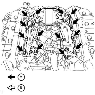
INSTALL NO. 1 WATER BY-PASS PIPE
-
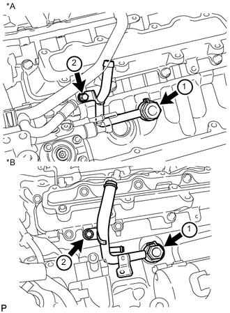
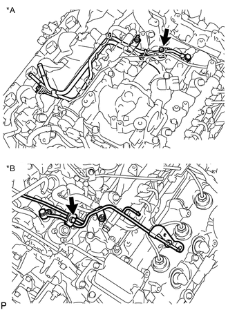
Text in Illustration *A w/ DPF *B w/o DPF Temporarily install a new gasket and the No. 1 water by-pass pipe with the union bolt and bolt.
-
Tighten the union bolt and bolt in the order shown in the illustration.
- Torque:
- for union bolt
- 59 N*m { 600 kgf*cm, 43 ft.*lbf }
- for bolt
- 10 N*m { 102 kgf*cm, 7 ft.*lbf }
-
-
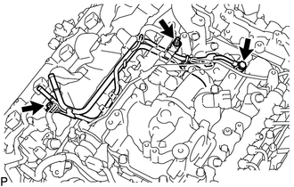
INSTALL FUEL TUBE SUB-ASSEMBLY (w/ DPF)
-
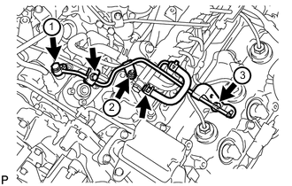
Attach the 3 clamps to install the fuel tube.
-
Connect the 3 fuel tube connectors Click here.
-
-
INSTALL FUEL COOLER ASSEMBLY (w/o DPF)
-
CONNECT NO. 6 WATER BY-PASS HOSE (w/o DPF)
-
INSTALL NO. 4 NOZZLE LEAKAGE PIPE (w/o DPF)
-
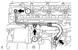
Temporarily install a new gasket and the No. 4 nozzle leakage pipe with the union bolt and bolt.
-
Tighten the union bolt and bolt in the order shown in the illustration.
- Torque:
- for union bolt
- 21 N*m { 214 kgf*cm, 15 ft.*lbf }
- for bolt
- 10 N*m { 102 kgf*cm, 7 ft.*lbf }
-
Connect the No. 2 fuel hose to the fuel cooler.
-
-
INSTALL NO. 3 NOZZLE LEAKAGE PIPE (w/o DPF)
-
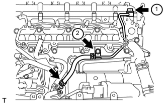
Temporarily install a new gasket and the No. 3 nozzle leakage pipe with the union bolt and bolt.
-
Tighten the union bolt and bolt in the order shown in the illustration.
- Torque:
- for union bolt
- 21 N*m { 214 kgf*cm, 15 ft.*lbf }
- for bolt
- 10 N*m { 102 kgf*cm, 7 ft.*lbf }
-
Connect the No. 1 fuel hose to the fuel cooler.
-
-
INSTALL EGR COOLER INSULATOR (w/ EGR System)
-
INSTALL EGR VALVE ASSEMBLY WITH EGR COOLER (w/ EGR System)
-
Connect the No. 5 water by-pass hose to the water by-pass outlet.
-
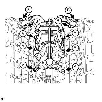
Install 2 new gaskets and the EGR valve with EGR cooler with the 6 bolts labeled A and 4 bolts labeled B shown in the illustration.
- Torque:
- for bolt A
- 21 N*m { 214 kgf*cm, 15 ft.*lbf }
- for bolt B
- 29 N*m { 296 kgf*cm, 21 ft.*lbf }
Tech Tips
The gasket claws should face toward the No. 1 and No. 2 EGR pipes.
-
-
INSTALL EGR PIPE INSULATOR (w/ EGR System)
-
Install the EGR pipe insulator with the 2 bolts.
- Torque:
- 21 N*m { 214 kgf*cm, 15 ft.*lbf }
Note
If the No. 1 and No. 2 EGR pipe insulator installation stay is deformed, or the bolt holes of the EGR pipe insulator do not align, replace the No. 1 and No. 2 EGR pipes as a set.
-
-
INSTALL INTAKE MANIFOLD INSULATOR (w/ EGR System)
-
INSTALL NO. 3 INTAKE MANIFOLD
-
Install 2 new gaskets to the No. 1 and No. 2 intake manifolds.
-
Install the No. 3 intake manifold with the 16 bolts.
- Torque:
- 21 N*m { 214 kgf*cm, 15 ft.*lbf }
Bolt Length Item Length Bolt A 25 mm (0.984 in.) Bolt B 70 mm (2.76 in.)
-
-
CONNECT NO. 2 ENGINE WIRE
-
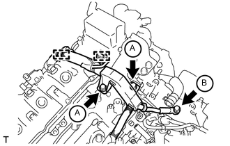
Connect the No. 2 engine wire with the 3 bolts.
- Torque:
- for bolt A
- 13 N*m { 133 kgf*cm, 10 ft.*lbf }
- for bolt B
- 32 N*m { 326 kgf*cm, 24 ft.*lbf }
-
Attach the 2 wire harness clamps.
-
-
INSTALL INTAKE PIPE
-
w/ EGR System:
Install 2 new gaskets and the intake pipe with the 6 bolts and 2 nuts.
- Torque:
- 21 N*m { 214 kgf*cm, 15 ft.*lbf }
-
w/o EGR System:
Install a new gasket and the intake pipe with the 4 bolts and 2 nuts.
- Torque:
- 21 N*m { 214 kgf*cm, 15 ft.*lbf }
-
-
INSTALL NO. 2 INTAKE MANIFOLD INSULATOR (w/ Intercooler)
-
INSTALL NO. 1 INTAKE MANIFOLD INSULATOR (w/ Intercooler)
-
INSTALL NO. 1 NOZZLE LEAKAGE PIPE (w/ DPF)
-
INSTALL NO. 2 NOZZLE LEAKAGE PIPE (w/ DPF)
-
INSTALL NO. 3 NOZZLE LEAKAGE PIPE (w/ DPF)
-
Temporarily install 2 new gaskets and the No. 3 nozzle leakage pipe with the 2 injector hollow screws and 3 bolts.
-
Tighten the 2 injector hollow screws and 3 bolts.
- Torque:
- for injector hollow screw
- 21 N*m { 214 kgf*cm, 15 ft.*lbf }
- for bolt
- 21 N*m { 214 kgf*cm, 15 ft.*lbf }
Tech Tips
Tighten the injector hollow screws first, and then tighten the bolts.
-
-
INSTALL CONNECTING WIRE (w/ DPF)
-
Attach the 2 clamps to install the connecting wire.
-
-
INSTALL COMMON RAIL ASSEMBLY RH
-
INSTALL INJECTION PIPE RH
-
Using a union nut wrench, install 4 new injection pipes.
- Torque:
- 34 N*m { 347 kgf*cm, 25 ft.*lbf }
Note
-
Make sure there is no damage or foreign matter on the seal surfaces.
-
Use the formula to calculate special torque values for situations where a union nut wrench is combined with a torque wrench Click here.
-
w/ Intercooler:
Install the 4 injection pipe clamps with the 2 nuts.
- Torque:
- 5.0 N*m { 51 kgf*cm, 44 in.*lbf }
-
-
INSTALL NO. 1 FUEL INJECTOR PROTECTOR (w/ DPF)
-
INSTALL NO. 2 FUEL INJECTOR PROTECTOR (w/ DPF)
-
INSTALL CYLINDER HEAD COVER SILENCER RH (w/ DPF)
-
INSTALL NO. 5 INJECTION PIPE SUB-ASSEMBLY
-
Temporarily install a new No. 5 injection pipe by hand.
Note
Make sure there is no damage or foreign matter on the seal surfaces.
-
w/ DPF:
Temporarily install the used gasket and fuel filter to injection pump fuel pipe with the nut, bolt and union bolt.
-
w/o DPF:
Temporarily install the used gasket and No. 2 fuel pipe with the nut, bolt and union bolt.
-
Text in Illustration *A w/ DPF *B w/o DPF Install the No. 2 injection pipe clamp with the bolt.
- Torque:
- 5.0 N*m { 51 kgf*cm, 44 in.*lbf }
-
Using a union nut wrench, tighten the No. 5 injection pipe ends.
- Torque:
- 34 N*m { 347 kgf*cm, 25 ft.*lbf }
Note
Use the formula to calculate special torque values for situations where a union nut wrench is combined with a torque wrench Click here.
-
Remove the bolt and No. 2 injection pipe clamp.
-
Remove the union bolt and gasket.
-
w/ DPF:
Remove the bolt, nut and fuel filter to injection pump fuel pipe.
-
w/o DPF:
Remove the bolt, nut and No. 2 fuel pipe.
-
-
CONNECT FUEL PUMP MOTOR WIRE
-
Install the fuel pump motor wire bracket to the No. 3 intake manifold with the bolt.
- Torque:
- 10 N*m { 102 kgf*cm, 7 ft.*lbf }
-
Connect the connector to the fuel supply pump.
-
-
INSTALL FUEL FILTER TO INJECTION PUMP FUEL PIPE SUB-ASSEMBLY
-
w/ DPF:
Note
Check for damage and foreign matter on the fuel pipe installation surface of the fuel supply pump.
If there is foreign matter, remove it from the installation surface.
If the installation surface is damaged, replace the fuel supply pump.
-
Temporarily install a new gasket and fuel filter to injection pump fuel pipe with the nut, bolt and union bolt.
-
Install the No. 2 injection pipe clamp with the bolt.
- Torque:
- 4.0 N*m { 41 kgf*cm, 35 in.*lbf }
-
Tighten the union bolt, bolt and nut.
- Torque:
- for union bolt
- 12 N*m { 125 kgf*cm, 9 ft.*lbf }
- for bolt and nut
- 10 N*m { 102 kgf*cm, 7 ft.*lbf }
-
Connect the fuel hose.
-
-
w/o DPF:
-
Install the fuel filter to injection pump fuel pipe with the bolt.
- Torque:
- 10 N*m { 102 kgf*cm, 7 ft.*lbf }
-
Connect the 2 hoses to the fuel pipe.
-
-
-
INSTALL COMMON RAIL ASSEMBLY LH
-
INSTALL NO. 5 NOZZLE LEAKAGE PIPE (w/ DPF)
-
INSTALL NO. 2 FUEL PIPE (w/ DPF)
-
INSTALL INJECTION PIPE LH
-
Using a union nut wrench, install the 4 new injection pipes.
- Torque:
- 34 N*m { 347 kgf*cm, 25 ft.*lbf }
Note
-
Make sure there is no damage or foreign matter on the seal surfaces.
-
Use the formula to calculate special torque values for situations where a union nut wrench is combined with a torque wrench Click here.
-
w/ Intercooler:
Install the 4 injection pipe clamps with the 2 nuts.
- Torque:
- 5.0 N*m { 51 kgf*cm, 44 in.*lbf }
-
-
INSTALL NO. 4 NOZZLE LEAKAGE PIPE (w/ DPF)
-
Temporarily install a new gasket and No. 4 nozzle leakage pipe with the fuel check valve.
-
Tighten the fuel check valve.
- Torque:
- 32 N*m { 321 kgf*cm, 23 ft.*lbf }
-
Connect the fuel hose.
-
-
INSTALL CYLINDER HEAD COVER SILENCER LH (w/ DPF)
-
INSTALL NO. 1 VACUUM TRANSMITTING PIPE SUB-ASSEMBLY (w/ DPF)
-
INSTALL NO. 1 VACUUM SWITCHING VALVE ASSEMBLY (w/ DPF)
-
CONNECT NO. 6 INJECTION PIPE SUB-ASSEMBLY
-
w/ EGR System:
-
Temporarily install a new No. 6 injection pipe to the common rail LH and RH.
Note
Make sure there is no damage or foreign matter on the seal surfaces.
-
Install the 2 No. 2 injection pipe clamps with the 2 nuts.
- Torque:
- 5.0 N*m { 51 kgf*cm, 44 in.*lbf }
-
Using a union nut wrench, tighten the No. 6 injection pipe ends.
- Torque:
- 34 N*m { 347 kgf*cm, 25 ft.*lbf }
Note
Use the formula to calculate special torque values for situations where a union nut wrench is combined with a torque wrench Click here.
-
-
w/o EGR System:
-
Temporarily install a new No. 6 injection pipe to the common rail LH and RH.
Note
Make sure there is no damage or foreign matter on the seal surfaces.
-
Install the bracket to the No. 3 intake manifold with the bolt.
- Torque:
- 10 N*m { 102 kgf*cm, 7 ft.*lbf }
-
Install the No. 2 injection pipe clamp with the nut.
- Torque:
- 5.0 N*m { 51 kgf*cm, 44 in.*lbf }
-
Using a union nut wrench, tighten the No. 6 injection pipe ends.
- Torque:
- 34 N*m { 347 kgf*cm, 25 ft.*lbf }
Note
Use the formula to calculate special torque values for situations where a union nut wrench is combined with a torque wrench Click here.
-
-
-
INSTALL NO. 2 FUEL PIPE SUB-ASSEMBLY (w/o DPF)
Note
Check for damage and foreign matter on the fuel pipe installation surface of the supply pump.
If there is foreign matter, remove it from the installation surface. If the installation surface is damaged, replace the fuel supply pump.
-
Temporarily install a new gasket and the No. 2 fuel pipe with the union bolt, nut and bolt.
-
Tighten the union bolt, nut and bolt in the order shown in the illustration.
- Torque:
- for union bolt
- 25 N*m { 255 kgf*cm, 18 ft.*lbf }
- for bolt and nut
- 10 N*m { 102 kgf*cm, 7 ft.*lbf }
-
Install the No. 2 injection pipe clamp with the bolt.
- Torque:
- 4.0 N*m { 41 kgf*cm, 35 in.*lbf }
-
Connect the fuel hose to the No. 5 nozzle leakage pipe.
-
-
CONNECT ENGINE WIRE
-
LH Side:
-
Install the engine wire protector with the 2 bolts.
-
Connect the 8 connectors.
-
Attach the wire harness clamp.
-
Install the engine wire harness bracket with the bolt.
-
for RHD:
Connect the wire harness with the wire harness clamp holder.
-
Attach the 3 wire harness clamps and connect the 2 connectors.
-
Attach the 3 wire harness clamps and connect the 4 connectors.
-
-
RH Side:
-
Install the engine wire harness protector with the 3 bolts.
-
Connect the 7 connectors.
-
Attach the wire harness clamp.
-
Install the wire harness bracket with the bolt.
-
Install the glow plug wire harness with the nut and screw grommet.
- Torque:
- 4.0 N*m { 41 kgf*cm, 35 in.*lbf }
-
for RHD:
Install the wire harness clamp holder with the bolt.
-
for RHD:
Connect the wire harness with the wire harness clamp holder.
-
-
Rear Side:
-
Install the glow plug wire harness with the nut and screw grommet.
- Torque:
- 4.0 N*m { 41 kgf*cm, 35 in.*lbf }
-
w/ DPF:
Connect the 3 connectors.
-
w/o DPF:
Connect the connector.
-
Install the engine wire harness protector with the 2 bolts.
-
Install the 2 ground wires with the 2 bolts.
- Torque:
- 8.4 N*m { 87 kgf*cm, 74 in.*lbf }
-
Attach the wire harness clamp.
-
-
-
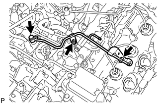
INSTALL NO. 4 WATER BY-PASS PIPE
-
w/ EGR System:
-
w/ DPF:
Connect the 3 water hose ends, and temporarily install the No. 4 water by-pass pipe with the 2 bolts and nut.
-
w/o DPF:
Connect the 4 water hose ends, and temporarily install the No. 4 water by-pass pipe with the 2 bolts and nut.
-
-
w/o EGR System:
Connect the 3 water hose ends, and temporarily install the No. 4 water by-pass pipe with the 2 bolts and nut.
-
First tighten the 2 bolts and then tighten the nut.
- Torque:
- 10 N*m { 102 kgf*cm, 7 ft.*lbf }
-
-
INSTALL NO. 3 WATER BY-PASS PIPE (w/o Viscous Heater)
-
Connect the 2 water hose ends, and install the No. 3 water by-pass pipe with the 2 bolts.
- Torque:
- 10 N*m { 102 kgf*cm, 7 ft.*lbf }
-
-
CONNECT FUEL HOSE
-
INSTALL NO. 1 AIR CLEANER PIPE SUB-ASSEMBLY
-
Connect the No. 1 air cleaner pipe to the No. 1 intake air connector pipe.
-
Install the pipe with the bolt.
- Torque:
- 21 N*m { 214 kgf*cm, 15 ft.*lbf }
-
Tighten the hose clamp.
- Torque:
- 6.3 N*m { 64 kgf*cm, 56 in.*lbf }
-
-
INSTALL HEATER WATER PIPE SUB-ASSEMBLY (w/ Viscous Heater)
-
Connect the 4 water hose ends, and install the water pipe with the 4 bolts.
- Torque:
- 9.8 N*m { 100 kgf*cm, 87 in.*lbf }
-
-
INSTALL NO. 2 AIR CLEANER PIPE SUB-ASSEMBLY
-
Connect the No. 2 air cleaner pipe to the No. 2 intake air connector pipe.
-
Connect the ventilation hose to the oil separator.
-
Install the pipe with the bolt.
- Torque:
- 21 N*m { 214 kgf*cm, 15 ft.*lbf }
-
Tighten the hose clamp.
- Torque:
- 6.3 N*m { 64 kgf*cm, 56 in.*lbf }
-
-
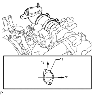
INSTALL NO. 4 AIR TUBE
-
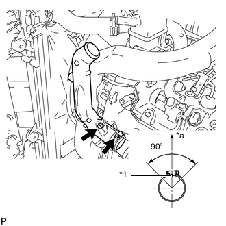
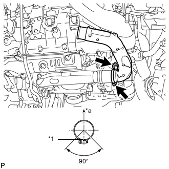
Text in Illustration *1 Paint Mark *a Top Install the No. 4 air tube with the bolt.
- Torque:
- 21 N*m { 214 kgf*cm, 15 ft.*lbf }
-
Tighten the hose clamp.
- Torque:
- 6.3 N*m { 64 kgf*cm, 56 in.*lbf }
Tech Tips
Make sure the direction of the hose clamp is as shown in the illustration.
-
Install the suction hose with the bolt.
- Torque:
- 9.8 N*m { 100 kgf*cm, 87 in.*lbf }
-
-
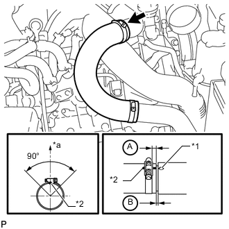
INSTALL NO. 2 AIR HOSE
-
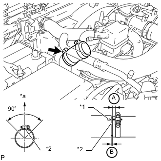
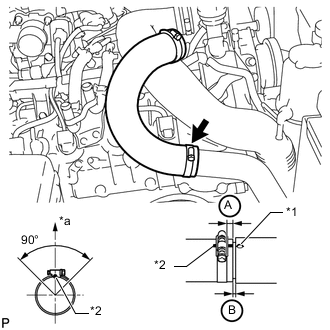
Text in Illustration *1 Protrusion *2 Paint Mark *a Top Connect the No. 2 air hose with the hose clamp.
- Torque:
- 6.3 N*m { 64 kgf*cm, 56 in.*lbf }
Tech Tips
-
Align the paint mark of the air hose with the protrusion and push on the air hose so that distance B is 0 to 3 mm (0 to 0.118 in.).
-
Position the clamp so that distance A is 2 to 6 mm (0.0787 to 0.236 in.).
-
Make sure the direction of the hose clamp is as shown in the illustration.
-
-
INSTALL NO. 3 AIR TUBE
-
Text in Illustration *1 Paint Mark *a Top Install the No. 3 air tube with the bolt.
- Torque:
- 21 N*m { 214 kgf*cm, 15 ft.*lbf }
-
Tighten the hose clamp.
- Torque:
- 6.3 N*m { 64 kgf*cm, 56 in.*lbf }
Tech Tips
Make sure the direction of the hose clamp is as shown in the illustration.
-
Install the wire harness bracket with the bolt.
-
Install the ground wire with the nut, and attach the wire harness clamp.
- Torque:
- 8.4 N*m { 85 kgf*cm, 74 in.*lbf }
-
-
INSTALL NO. 1 AIR HOSE
-
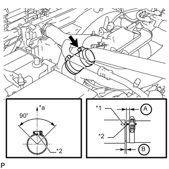
Text in Illustration *1 Protrusion *2 Paint Mark *a Top Connect the No. 1 air hose with the hose clamp.
- Torque:
- 6.3 N*m { 64 kgf*cm, 56 in.*lbf }
Tech Tips
-
Align the paint mark of the air hose with the protrusion and push on the air hose so that distance B is 0 to 3 mm (0 to 0.118 in.).
-
Position the clamp so that distance A is 2 to 6 mm (0.0787 to 0.236 in.).
-
Make sure the direction of the hose clamp is as shown in the illustration.
-
-
INSTALL INTAKE AIR CONNECTOR
-
Connect the intake air connector to the No. 1 and No. 2 air cleaner pipes.
-
Install the connector with the 2 bolts.
- Torque:
- 21 N*m { 214 kgf*cm, 15 ft.*lbf }
-
Tighten the 2 hose clamps.
- Torque:
- 6.3 N*m { 64 kgf*cm, 56 in.*lbf }
-
Attach the 3 wire harness clamps.
-
w/o Viscous Heater:
Connect the connector to the water temperature sensor.
-
w/ Viscous Heater:
Connect the 2 connectors to the water temperature sensor and viscous with magnet clutch heater.
-
-
TEMPORARILY INSTALL NO. 1 AIR CLEANER HOSE
-
Temporarily install the air cleaner hose to the intake air connector.
-
-
INSTALL AIR CLEANER CAP SUB-ASSEMBLY
-
Connect the air cleaner cap to the air cleaner hose, and install the air cleaner cap with the 4 clamps.
-
Connect the mass air flow meter connector and attach the wire harness clamp to the air cleaner cap.
-
Attach the wire harness clamp.
-
Align the protrusion of the air cleaner cap and the concave portion of the air cleaner hose.
-
Tighten the 2 hose clamps.
- Torque:
- 2.5 N*m { 25 kgf*cm, 22 in.*lbf }
-
-
INSTALL DIESEL THROTTLE BODY ASSEMBLY LH
-
INSTALL NO. 3 INTERCOOLER SUPPORT BRACKET
-
INSTALL NO. 1 GAS FILTER
-
INSTALL TUBE CONNECTOR TO FLEXIBLE HOSE TUBE (for Manual Transmission)
-
INSTALL AIR TUBE SUB-ASSEMBLY LH
-
INSTALL CLUTCH HOSE (for Manual Transmission)
-
INSTALL DIESEL THROTTLE BODY ASSEMBLY RH
-
INSTALL AIR TUBE SUB-ASSEMBLY RH
-
INSTALL NO. 2 ENGINE OIL LEVEL DIPSTICK GUIDE
-
Apply a light coat of engine oil to a new O-ring.
-
Install the O-ring to the No. 2 engine oil level dipstick guide.
-
Install the No. 2 engine oil level dipstick guide with the 2 bolts.
- Torque:
- 10 N*m { 102 kgf*cm, 7 ft.*lbf }
-
Connect the ventilation hose to the cylinder head cover RH.
-
Connect the wire harness clamp to the No. 2 engine oil level dipstick guide bracket.
-
-
CONNECT WATER HOSE SUB-ASSEMBLY
-
INSTALL NO. 2 COOL AIR INLET (w/o Intercooler)
-
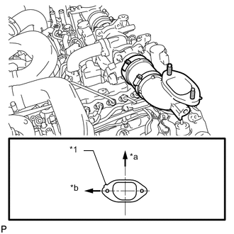
Text in Illustration *1 Protrusion *a Front *b LH Side Install a new gasket to the air tube LH.
Tech Tips
Install the gasket with the protrusion facing as shown in the illustration.
-
Install the No. 2 cool air inlet with the 3 nuts and bolt.
- Torque:
- 21 N*m { 214 kgf*cm, 15 ft.*lbf }
-
Text in Illustration *1 Protrusion *2 Paint Mark *a Top Connect the No. 2 air hose to the No. 2 cool air inlet.
-
Tighten the No. 2 air hose clamp.
- Torque:
- 6.3 N*m { 64 kgf*cm, 56 in.*lbf }
Tech Tips
-
Align the paint mark of the air hose with the protrusion and push on the air hose so that distance B is 0 to 3 mm (0 to 0.118 in.).
-
Position the clamp so that distance A is 2 to 6 mm (0.0787 to 0.236 in.).
-
Make sure the direction of the hose clamp is as shown in the illustration.
-
-
INSTALL NO. 1 COOL AIR INLET (w/o Intercooler)
-
Text in Illustration *1 Protrusion *a Front *b RH Side Install a new gasket to the air tube RH.
Tech Tips
Install the gasket with the protrusion facing as shown in the illustration.
-
Install the No. 1 cool air inlet with the 3 nuts and bolt.
- Torque:
- 21 N*m { 214 kgf*cm, 15 ft.*lbf }
-
Connect the vacuum hose, intake air temperature sensor connector and turbo pressure sensor connector.
-
Text in Illustration *1 Protrusion *2 Paint Mark *a Top Connect the No. 1 air hose to the No. 1 cool air inlet.
-
Tighten the No. 1 air hose clamp.
- Torque:
- 6.3 N*m { 64 kgf*cm, 56 in.*lbf }
Tech Tips
-
Align the paint mark of the air hose with the protrusion and push on the air hose so that distance B is 0 to 3 mm (0 to 0.118 in.).
-
Position the clamp so that distance A is 2 to 6 mm (0.0787 to 0.236 in.).
-
Make sure the direction of the hose clamp is as shown in the illustration.
-
-
INSTALL INTERCOOLER ASSEMBLY (w/ Intercooler)
-
BLEED CLUTCH LINE
-
CHECK FOR CLUTCH FLUID LEAK
-
CONNECT CABLE TO NEGATIVE BATTERY TERMINAL
Note
When disconnecting the cable, some systems need to be initialized after the cable is reconnected Click here.
-
Connect the cables to the negative (-) main battery and sub-battery terminals.
-
-
ADD ENGINE COOLANT
-
INSPECT FOR FUEL LEAK
-
CHECK FOR ENGINE COOLANT LEAK
-
INSPECT FOR OIL LEAK
-
INSTALL UPPER RADIATOR SUPPORT SEAL
-
INSTALL NO. 1 ENGINE UNDER COVER SUB-ASSEMBLY
-
INSTALL FRONT FENDER SPLASH SHIELD SUB-ASSEMBLY RH
-
INSTALL FRONT FENDER SPLASH SHIELD SUB-ASSEMBLY LH