EXHAUST MANIFOLD REMOVAL
PROCEDURE
-
REMOVE V-BANK COVER SUB-ASSEMBLY
-
REMOVE AIR CLEANER AND HOSE
-
REMOVE FRONT FENDER SPLASH SHIELD SUB-ASSEMBLY LH
-
REMOVE FRONT FENDER SPLASH SHIELD SUB-ASSEMBLY RH
-
REMOVE NO. 1 ENGINE UNDER COVER SUB-ASSEMBLY
-
REMOVE NO. 2 ENGINE UNDER COVER
-
REMOVE FRONT FENDER APRON TRIM PACKING B
-
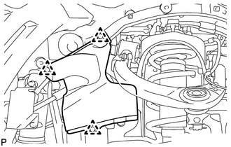
w/ KDSS:
Remove the 3 clips and front fender apron trim packing B.
-
w/o KDSS:
Remove the 4 clips and front fender apron trim packing B.
-
-
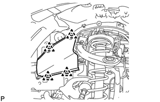
REMOVE FRONT FENDER APRON TRIM PACKING D
-
Remove the 4 clips and front fender apron trim packing D.
-
-
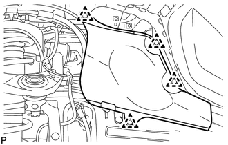
REMOVE FRONT FENDER APRON TRIM PACKING A
-
Remove the 3 clips and front fender apron trim packing A.
-
-
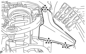
REMOVE FRONT FENDER APRON TRIM PACKING C
-
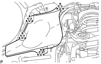
Remove the 4 clips and front fender apron trim packing C.
-
-
REMOVE FRONT EXHAUST PIPE ASSEMBLY
-
REMOVE FRONT PROPELLER SHAFT ASSEMBLY
-
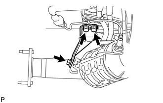
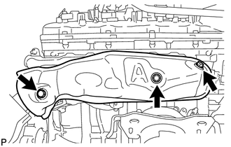
REMOVE PROPELLER SHAFT HEAT INSULATOR
-
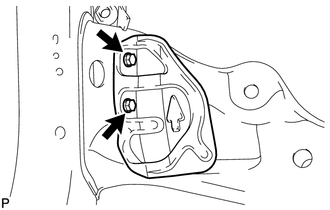
Remove the 2 bolts and heat insulator.
-
-
REMOVE NO. 2 MANIFOLD STAY
-
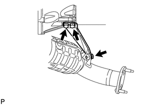
Remove the 3 bolts and No. 2 manifold stay.
-
-
REMOVE NO. 2 EXHAUST MANIFOLD HEAT INSULATOR
-
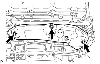
Remove the 3 bolts and No. 2 exhaust manifold heat insulator.
-
-
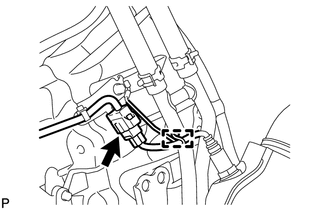
REMOVE EXHAUST MANIFOLD ASSEMBLY LH
-
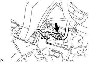
Disconnect the air fuel ratio sensor connector and detach the wire harness clamp.
-
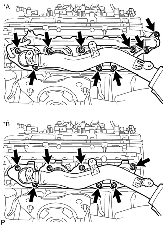
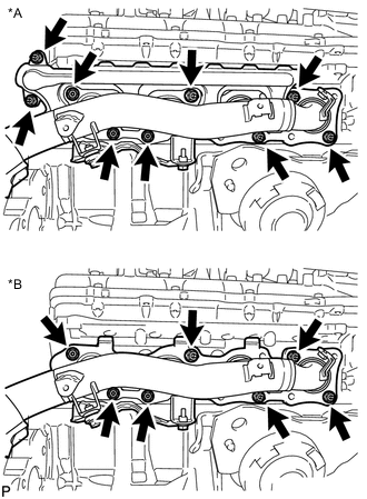
Text in Illustration *A w/ Secondary Air Injection System *B w/o Secondary Air Injection System w/ Secondary Air Injection System:
Remove the 9 nuts, exhaust manifold and 2 gaskets.
-
w/o Secondary Air Injection System:
Remove the 7 nuts, exhaust manifold and gasket.
-
-
REMOVE MANIFOLD STAY
-
Remove the 3 bolts and manifold stay.
-
-
REMOVE ENGINE OIL LEVEL DIPSTICK GUIDE
-
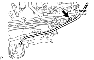
Remove the engine oil level dipstick.
-
Detach the engine wire clamp.
-
Remove the bolt and engine oil level dipstick guide.
-
Remove the O-ring from the engine oil level dipstick guide.
-
-
REMOVE NO. 1 EXHAUST MANIFOLD HEAT INSULATOR
-
Remove the 3 bolts and heat insulator.
-
-
REMOVE EXHAUST MANIFOLD ASSEMBLY RH
-
Disconnect the air fuel ratio sensor connector and detach the wire harness clamp.
-
Text in Illustration *A w/ Secondary Air Injection System *B w/o Secondary Air Injection System w/ Secondary Air Injection System:
Remove the 9 nuts, exhaust manifold and 2 gaskets.
-
w/o Secondary Air Injection System:
Remove the 7 nuts, exhaust manifold and 2 gaskets.
-
-
REMOVE AIR FUEL RATIO SENSOR (for Bank 1 Sensor 1)
-
REMOVE AIR FUEL RATIO SENSOR (for Bank 2 Sensor 1)