PROCEDURE
- Click here
INSTALL STUD BOLT
Note:If a stud bolt is deformed or its threads are damaged, replace it.
-
Using the E8 "TORX" socket wrench, install the 2 stud bolts.
8.0 N*m 82 kgf*cm 71 in.*lbf
-
- Click here
INSTALL INTAKE MANIFOLD
-
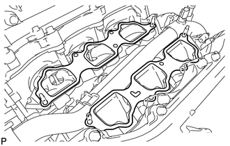
Set a new gasket on each cylinder head.
Note:
-
Align the port holes of the gasket and cylinder head.
-
Be careful of the installation direction.
-
-
Set the intake manifold on the cylinder heads.
-
Install and uniformly tighten the 6 bolts and 4 nuts in several passes.
21 N*m 214 kgf*cm 15 ft.*lbf Tip:Tighten the inner installation bolts of the intake manifold before tightening the outer bolts.
-
- Click here
INSTALL FUEL DELIVERY PIPE SUB-ASSEMBLY
- Click here
INSTALL INTAKE AIR SURGE TANK
-
Install a new gasket to the intake air surge tank.
-
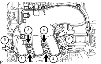
Install the intake air surge tank with the 4 bolts and 2 nuts in the order shown in the illustration.
28 N*m 286 kgf*cm 21 ft.*lbf Table 1. Text in Illustration 
Bolt 
Nut -
Install the throttle body bracket with the 2 bolts.
21 N*m 214 kgf*cm 15 ft.*lbf -
Install the No. 1 surge tank stay with the 2 bolts.
21 N*m 214 kgf*cm 15 ft.*lbf -
Attach the wire harness clamp.
-
Install the bracket with the bolt and attach the 2 wire harness clamps.
8.0 N*m 82 kgf*cm 71 in.*lbf -
Install the No. 2 surge tank stay with the 2 bolts.
21 N*m 214 kgf*cm 15 ft.*lbf -
for Manual Transmission:
Connect the clutch flexible hose bracket with the nut.
20 N*m 204 kgf*cm 15 ft.*lbf -
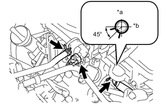
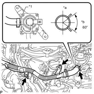
Connect the No. 1 PCV hose.
Table 2. Text in Illustration *a Front *b RH Tip:Connect the No. 1 PCV hose so that the direction of the hose clamp is as indicated in the illustration.
-
Connect the No. 1 vacuum switching valve connector.
-
Connect the purge line hose.
-
Connect the throttle body connector.
-
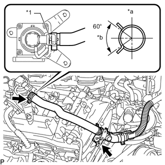
Connect the No. 4 water by-pass hose.
-
Connect the No. 5 water by-pass hose.
-
- Click here
INSTALL AIR TUBE (w/ Secondary Air Injection System)
-
for Bank 1 Side:
Align the paint mark with the projection and connect the air tube assembly to the emission control valve set.
Table 3. Text in Illustration *1 Paint Mark *a Top *b RH Side Tip:Make sure the direction of the hose clamp is as shown in the illustration.
-
for Bank 2 Side:
Align the paint mark with the projection and connect the air tube assembly to the No. 2 emission control valve set.
Table 4. Text in Illustration *1 Paint Mark *a Top *b LH Side Tip:Make sure the direction of the hose clamp is as shown in the illustration.
-
Install the 3 bolts.
10 N*m 102 kgf*cm 7 ft.*lbf -
Connect the No. 3 air hose.
-
- Click here
INSTALL NO. 1 AIR CLEANER HOSE
-
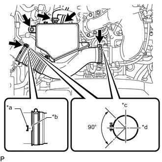
Install the No. 1 air cleaner hose with the 2 hose clamps.
2.5 N*m 25 kgf*cm 22 in.*lbf Table 5. Text in Illustration *a Protrusion *b Groove *c Top *d Front -
Install the bolt.
5.0 N*m 51 kgf*cm 44 in.*lbf -
Connect the vacuum hose and No. 2 PCV hose.
-
- Click here
CONNECT CABLE TO NEGATIVE BATTERY TERMINAL
Note:When disconnecting the cable, some systems need to be initialized after the cable is reconnected (Click here).
- Click here
ADD ENGINE COOLANT
- Click here
INSPECT FOR COOLANT LEAK
- Click here
INSPECT FOR FUEL LEAK
- Click here
INSTALL V-BANK COVER
-
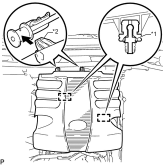
Attach the 2 V-bank cover hooks to the bracket. Then align the 2 V-bank cover grommets with the 2 pins and press down on the V-bank cover to attach the pins.
Table 6. Text in Illustration *1 Pin *2 Hook
-
- Click here
INSTALL NO. 1 ENGINE UNDER COVER SUB-ASSEMBLY
- Click here
INSTALL FRONT FENDER SPLASH SHIELD SUB-ASSEMBLY LH
- Click here
INSTALL FRONT FENDER SPLASH SHIELD SUB-ASSEMBLY RH