EXHAUST FUEL ADDITION INJECTOR(for DPF) REMOVAL
CAUTION / NOTICE / HINT
Note
When fuel lines are disconnected, air may enter the fuel lines, leading to engine starting trouble. Therefore, perform forced regeneration and bleed the air from the fuel lines.
PROCEDURE
-
PRECAUTION
Note
After turning the ignition switch off, waiting time may be required before disconnecting the cable from the battery terminal. Therefore, make sure to read the disconnecting the cable from the battery terminal notice before proceeding with work Click here.
-
DISCONNECT CABLE FROM NEGATIVE BATTERY TERMINAL
Note
When disconnecting the cable, some systems need to be initialized after the cable is reconnected Click here.
-
REMOVE FRONT FENDER SPLASH SHIELD SUB-ASSEMBLY LH
-
REMOVE FRONT FENDER SPLASH SHIELD SUB-ASSEMBLY RH
-
REMOVE NO. 1 ENGINE UNDER COVER SUB-ASSEMBLY
-
REMOVE UPPER RADIATOR SUPPORT SEAL
-
DRAIN ENGINE COOLANT
-
REMOVE INTERCOOLER ASSEMBLY
-
REMOVE AIR CLEANER CAP SUB-ASSEMBLY
-
REMOVE NO. 1 AIR CLEANER HOSE
-
REMOVE INTAKE AIR CONNECTOR
-
REMOVE NO. 2 ENGINE OIL LEVEL DIPSTICK GUIDE
-
REMOVE AIR TUBE SUB-ASSEMBLY RH
-
REMOVE DIESEL THROTTLE BODY ASSEMBLY RH
-
REMOVE AIR TUBE SUB-ASSEMBLY LH
-
REMOVE NO. 1 GAS FILTER
-
REMOVE NO. 3 INTERCOOLER SUPPORT BRACKET
-
REMOVE DIESEL THROTTLE BODY ASSEMBLY LH
-
REMOVE NO. 1 AIR HOSE
-
REMOVE NO. 3 AIR TUBE
-
REMOVE NO. 2 AIR HOSE
-
REMOVE NO. 4 AIR TUBE
-
REMOVE NO. 2 AIR CLEANER PIPE SUB-ASSEMBLY
-
DISCONNECT WATER HOSE SUB-ASSEMBLY
-
REMOVE HEATER WATER PIPE SUB-ASSEMBLY (w/ Viscous Heater)
-
REMOVE NO. 1 AIR CLEANER PIPE SUB-ASSEMBLY
-
DISCONNECT FUEL HOSE
-
REMOVE NO. 3 WATER BY-PASS PIPE (w/o Viscous Heater)
-
DISCONNECT ENGINE WIRE
-
REMOVE NO. 1 VACUUM SWITCHING VALVE ASSEMBLY
-
REMOVE NO. 1 VACUUM TRANSMITTING PIPE SUB-ASSEMBLY
-
REMOVE CYLINDER HEAD COVER SILENCER LH
-
REMOVE NO. 2 FUEL INJECTOR PROTECTOR
-
REMOVE CYLINDER HEAD COVER SILENCER RH
-
REMOVE NO. 1 FUEL INJECTOR PROTECTOR
-
REMOVE EXHAUST FUEL ADDITION INJECTOR ASSEMBLY
-
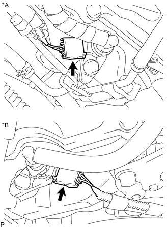
Text in Illustration *A for Bank 1 *B for Bank 2 Disconnect the 2 exhaust fuel addition injector connectors.
-
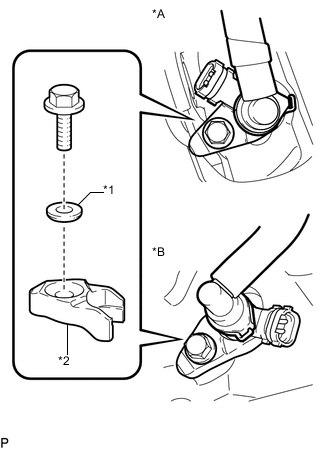
Text in Illustration *A for Bank 1 *B for Bank 2 *1 Washer *2 Nozzle Holder Clamp Remove the 2 bolts, 2 washers and 2 nozzle holder clamps.
-
Remove the 2 exhaust fuel addition injectors and 2 gaskets.
-
-
DISCONNECT FUEL TUBE SUB-ASSEMBLY
-
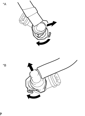
Text in Illustration *A for Bank 1 *B for Bank 2 Turn the 2 retainers shown in the illustration.
Note
-
Check for foreign matter on the fuel tube around the fuel tube connector. Clean it if necessary. Foreign matter can affect the ability of the O-ring to seal the fuel tube connector and fuel pipe.
-
Do not use any tools to separate the fuel tube connector and fuel pipe.
-
Do not forcefully bend, kink or twist the nylon tube.
-
Keep the fuel tube connector and fuel pipe free from foreign matter.
-
Put the fuel tube connector and fuel pipe in plastic bags to prevent damage and contamination.
-
-
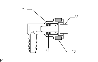
Text in Illustration *1 Fuel Tube Connector *2 Exhaust Fuel Addition Injector *3 Retainer *4 O-Ring Disconnect the 2 fuel tube connectors from the exhaust fuel addition injector.
-
-
REMOVE FUEL INJECTOR SEAL
-
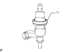
Text in Illustration *1 Fuel Injector Seal Remove the 2 fuel injector seals.
-