ТОПЛИВНАЯ ФОРСУНКА УСТАНОВКА

PROCEDURE
-
INSTALL FUEL INJECTOR ASSEMBLY
-
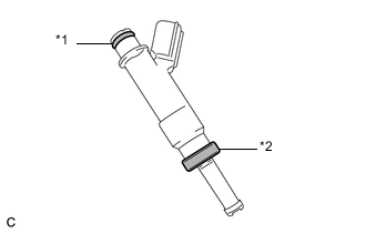
Text in Illustration *1 O-ring *2 Injector Vibration Insulator Install a new injector vibration insulator and O-ring to each fuel injector assembly.
-
Apply a light coat of gasoline or spindle oil to the contact surfaces of the new O-ring on each fuel injector assembly.
-
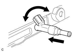
While turning the fuel injector assembly left and right, install it onto the fuel delivery pipe sub-assembly.
Note
-
Do not damage the fuel injector assembly or O-ring.
-
Do not twist the O-ring.
-
After installing each fuel injector, check that it turns smoothly. If not, replace the O-ring with a new one.
-
-
-
INSTALL NO. 1 DELIVERY PIPE SPACER
-
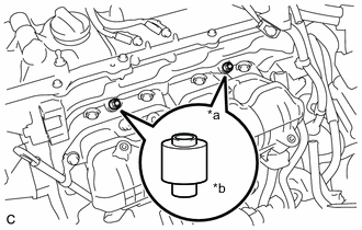
Text in Illustration *a Delivery Pipe Side *b Cylinder Head Side Install the 2 No. 1 delivery pipe spacers onto the cylinder head.
Note
Install the No. 1 delivery pipe spacers in the correct direction.
-
-
INSTALL FUEL DELIVERY PIPE SUB-ASSEMBLY
-
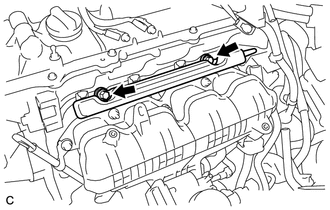
Install the fuel delivery pipe sub-assembly with the 4 fuel injector assemblies and install the 2 bolts.
- Torque:
- 21 N*m { 214 kgf*cm, 15 ft.*lbf }
Note
-
Do not drop the fuel injectors when installing the fuel delivery pipe sub-assembly.
-
Check that the fuel injector assemblies rotate smoothly after installing the fuel delivery pipe sub-assembly.
-
Install the bolt to secure the fuel delivery pipe sub-assembly.
- Torque:
- 21 N*m { 214 kgf*cm, 15 ft.*lbf }
-
-
INSTALL WATER BY-PASS PIPE
-
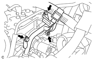
Install the water by-pass pipe with the 2 bolts and nut.
- Torque:
- 21 N*m { 214 kgf*cm, 15 ft.*lbf }
-
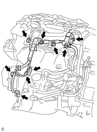
Engage the clamp to connect the wire harness.
-
-
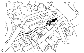
CONNECT FUEL TUBE SUB-ASSEMBLY
-
Push the fuel tube connector to the fuel pipe until the fuel tube connector makes a "click" sound.
Note
-
Before connecting the fuel tube connector and fuel pipe, check that there is no damage or foreign matter on the connecting part of the fuel pipe.
-
After connecting the fuel tube connector and fuel pipe, check that they are securely connected by trying to pull them apart.
-
-
Engage the lock claw to install the No. 1 fuel pipe clamp.
-
-
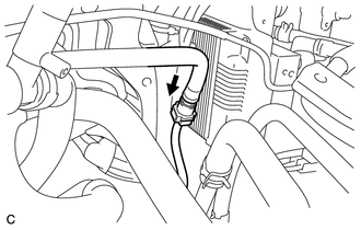
CONNECT ENGINE WIRE
-
Install the bolt.
- Torque:
- 8.3 N*m { 85 kgf*cm, 73 in.*lbf }
-
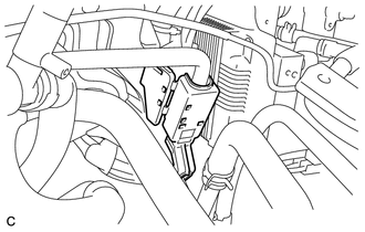
Connect the 4 fuel injector connectors.
-
Connect the 4 connectors.
-
Attach the 2 clamps to connect the wire harness.
-
-
INSTALL AIR CLEANER HOSE ASSEMBLY
-
INSTALL AIR CLEANER CASE
-
INSTALL INLET AIR CLEANER ASSEMBLY
-
INSTALL WATER HOSE HOSE CLAMP
-
INSTALL AIR CLEANER CAP SUB-ASSEMBLY
-
CONNECT CABLE TO NEGATIVE AUXILIARY BATTERY TERMINAL
Note
When disconnecting the cable, some systems need to be initialized after the cable is reconnected Click here.
-
INSPECT FOR FUEL LEAK
-
INSTALL REAR FLOOR BOARD UPPER NO. 3 PLATE
-
INSTALL DECK FLOOR BOX RH
-
INSTALL REAR NO. 3 FLOOR BOARD
-
INSTALL REAR DECK FLOOR BOX
-
INSTALL REAR NO. 2 FLOOR BOARD
-
INSTALL NO. 2 CYLINDER HEAD COVER
-
INSTALL RADIATOR SUPPORT OPENING COVER