REAR COMBINATION LIGHT ASSEMBLY ON-VEHICLE INSPECTION
PROCEDURE
-
INSPECT REAR COMBINATION LIGHT ASSEMBLY LH
-
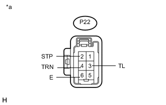
Text in Illustration *a Front view of wire harness connector
(to Rear Combination Light Assembly LH)
Disconnect the connector from the rear combination light assembly LH.
-
Measure the voltage according to the value(s) in the table below.
Standard Voltage Tester Connection Switch Condition Specified Condition P22-3 (TL) - P22-6 (E) Light control switch off Below 1 V Power switch off and light control switch in tail position 11 to 14 V P22-2 (STP) - P22-6 (E) Brake pedal released Below 1 V Power switch off and brake pedal depressed 11 to 14 V P22-4 (TRN)- P22-6 (E) Turn signal switch in neutral position Below 1 V Power switch on (IG) and turn signal switch in left turn position 11 to 14 V (60 to 120 times per minute) If the result is not as specified, repair or replace the wire harness or connector.
-
-
INSPECT REAR COMBINATION LIGHT ASSEMBLY RH
-
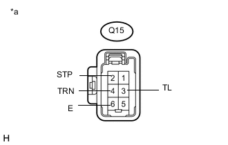
Text in Illustration *a Front view of wire harness connector
(to Rear Combination Light Assembly RH)
Disconnect the connector from the rear combination light assembly RH.
-
Measure the voltage according to the value(s) in the table below.
Standard Voltage Tester Connection Switch Condition Specified Condition Q15-3 (TL) - Q15-6 (E) Light control switch off Below 1 V Power switch off and light control switch in tail position 11 to 14 V Q15-2 (STP) - Q15-6 (E) Brake pedal released Below 1 V Power switch off and brake pedal depressed 11 to 14 V Q15-4 (TRN) - Q15-6 (E) Turn signal switch in neutral position Below 1 V Power switch on (IG) and turn signal switch in right turn position 11 to 14 V (60 to 120 times per minute) If the result is not as specified, repair or replace the wire harness or connector.
-