HEADLIGHT ASSEMBLY(for LED Headlight) INSPECTION
PROCEDURE
-
INSPECT FRONT TURN SIGNAL LIGHT SOCKET AND WIRE
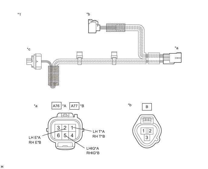
*A LH Side *B RH Side *1 Front Turn Signal Light Socket and Wire - - *a Component without harness connected
(to Wire Harness)
*b Component without harness connected
(to Headlight Leveling Motor)
*c Component without turn signal light installed
(to Turn Signal Light)
- -
-
Measure the resistance according to the value(s) in the table below.
-
Inspect the headlight leveling motor circuit. (LH Side)
Standard Resistance Tester Connection Condition Specified Condition A76-1 (LH T) - B-2 Always Below 1 Ω A76-2 (LH E) - B-1 Always Below 1 Ω A76-5 (LHIG) - B-3 Always Below 1 Ω If the result is not as specified, replace the front turn signal light socket and wire.
-
Inspect the headlight leveling motor circuit. (RH Side)
Standard Resistance Tester Connection Condition Specified Condition A77-1 (RH T) - B-2 Always Below 1 Ω A77-2 (RH E) - B-1 Always Below 1 Ω A77-5 (RHIG) - B-3 Always Below 1 Ω If the result is not as specified, replace the front turn signal light socket and wire.
-
-
-
INSPECT HEADLIGHT UNIT ASSEMBLY LH

*1 Headlight Unit Assembly LH - - *a Component without harness connected
(to Wire Harness)
*b Component without harness connected
(to Headlight Unit LH)
*c Component without harness connected
(to Electronic Light Source Control Gear)
*d Component without harness connected
(to Headlight Lens)
-
Measure the resistance according to the value(s) in the table below.
-
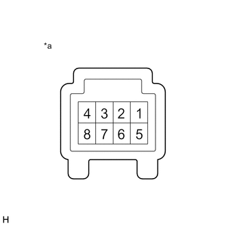
Inspect the Lo/Hi beam headlight light power source circuit.
Standard Resistance Tester Connection Condition Specified Condition A73-1 (S) - C-7 Always Below 1 Ω A73-5 (LO) - C-4 Always Below 1 Ω A73-6 (E) - C-2 Always Below 1 Ω If the result is not as specified, replace the headlight unit assembly LH.
-
Inspect the Lo/Hi beam shade circuit.
Standard Resistance Tester Connection Condition Specified Condition A73-2 (SOL) - C-3 Always Below 1 Ω If the result is not as specified, replace the headlight unit assembly LH.
-
Inspect the clearance light/daytime running light input circuit.
Standard Resistance Tester Connection Condition Specified Condition A73-3 (B) - D-1 Always Below 1 Ω A73-4 (E) - D-4 Always Below 1 Ω A73-7 (B) - D-7 Always Below 1 Ω If the result is not as specified, replace the headlight unit assembly LH.
-
Inspect the clearance light/daytime running light output circuit.
Standard Resistance Tester Connection Condition Specified Condition D-6 - E-1 Always Below 1 Ω D-9 - E-2 Always Below 1 Ω If the result is not as specified, replace the headlight unit assembly LH.
-
-
-
INSPECT HEADLIGHT UNIT LH
*a Component without harness connected
(Headlight Unit LH)
-
Apply auxiliary battery voltage to the headlight unit LH and check that the light illuminates.
OK Condition Specified Condition Auxiliary battery positive (+) → Terminal 4
Auxiliary battery negative (-) → Terminal 2
Lo/Hi beam headlight illuminates If the result is not as specified, replace the headlight unit LH.
-
Apply auxiliary battery voltage to the headlight unit LH and check that the Lo/Hi beam shade operates.
OK Condition Specified Condition Auxiliary battery positive (+) → Terminal 3
Auxiliary battery negative (-) → Terminal 2
Operates normally If the result is not as specified, replace the headlight unit LH.
-
-
INSPECT HEADLIGHT LENS LH
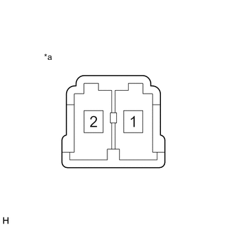
*a Component without harness connected
(Headlight Lens LH)
-
Apply auxiliary battery voltage to the headlight lens LH and check that the light illuminates.
OK Condition Specified Condition Auxiliary battery positive (+) → Terminal 2
Auxiliary battery negative (-) → Terminal 1
Clearance light/daytime running light illuminates If the result is not as specified, replace the headlight lens LH.
-
-
INSPECT HEADLIGHT UNIT ASSEMBLY RH
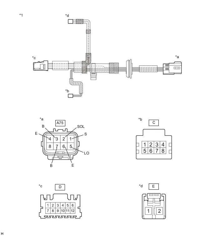
*1 Headlight Unit Assembly RH - - *a Component without harness connected
(to Wire Harness)
*b Component without harness connected
(to Headlight Unit RH)
*c Component without harness connected
(to Electronic Light Source Control Gear)
*d Component without harness connected
(to Headlight Lens)
-
Measure the resistance according to the value(s) in the table below.
-
Inspect the Lo/Hi beam headlight light power source circuit.
Standard Resistance Tester Connection Condition Specified Condition A75-1 (S) - C-7 Always Below 1 Ω A75-5 (LO) - C-4 Always Below 1 Ω A75-6 (E) - C-2 Always Below 1 Ω If the result is not as specified, replace the headlight unit assembly RH.
-
Inspect the Lo/Hi beam shade circuit.
Standard Resistance Tester Connection Condition Specified Condition A75-2 (SOL) - C-3 Always Below 1 Ω If the result is not as specified, replace the headlight unit assembly RH.
-
Inspect the clearance light/daytime running light input circuit.
Standard Resistance Tester Connection Condition Specified Condition A75-3 (B) - D-1 Always Below 1 Ω A75-4 (E) - D-4 Always Below 1 Ω A75-7 (B) - D-7 Always Below 1 Ω If the result is not as specified, replace the headlight unit assembly RH.
-
Inspect the clearance light/daytime running light output circuit.
Standard Resistance Tester Connection Condition Specified Condition D-6 - E-1 Always Below 1 Ω D-9 - E-2 Always Below 1 Ω If the result is not as specified, replace the headlight unit assembly RH.
-
-
-
INSPECT HEADLIGHT UNIT RH
*a Component without harness connected
(Headlight Unit RH)
-
Apply auxiliary battery voltage to the headlight unit RH and check that the light illuminates.
OK Condition Specified Condition Auxiliary battery positive (+) → Terminal 4
Auxiliary battery negative (-) → Terminal 2
Lo/Hi beam headlight illuminates If the result is not as specified, replace the headlight unit RH.
-
Apply auxiliary battery voltage to the headlight unit RH and check that the Lo/Hi beam shade operates.
OK Condition Specified Condition Auxiliary battery positive (+) → Terminal 3
Auxiliary battery negative (-) → Terminal 2
Operates normally If the result is not as specified, replace the headlight unit RH.
-
-
INSTALL HEADLIGHT LENS RH
*a Component without harness connected
(Headlight Lens RH)
-
Apply auxiliary battery voltage to the headlight lens RH and check that the light illuminates.
OK Condition Specified Condition Auxiliary battery positive (+) → Terminal 2
Auxiliary battery negative (-) → Terminal 1
Clearance light/daytime running light illuminates If the result is not as specified, replace the headlight lens RH.
-