LIGHTING SYSTEM Speed Signal Circuit
DESCRIPTION
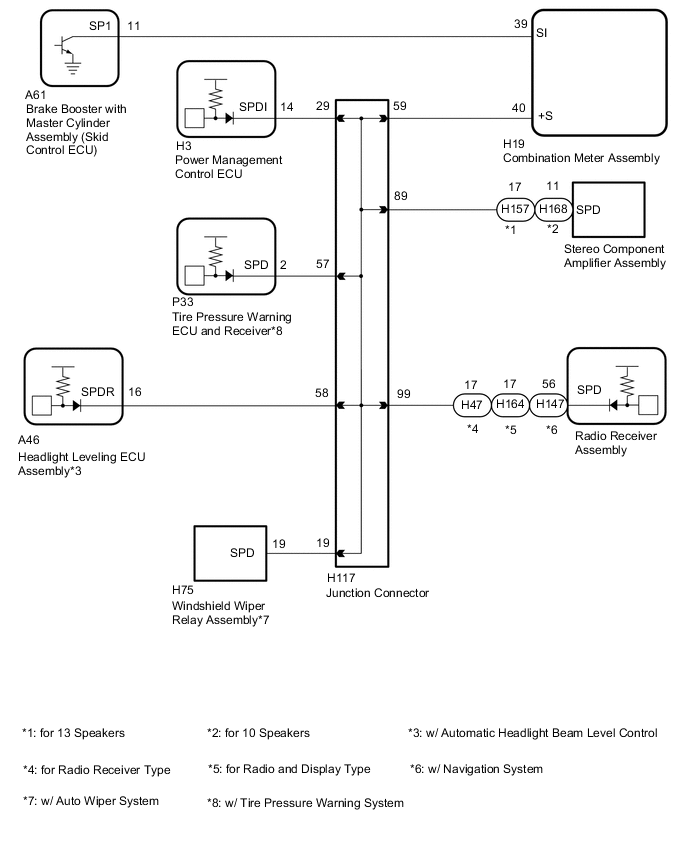
The headlight leveling ECU assembly receives the vehicle speed signal from the combination meter assembly.
Tech Tips
-
A voltage of 12 V or 5 V is output from each ECU and then input to the combination meter. The signal is changed to a pulse signal at the transistor in the combination meter. Each ECU controls the respective system based on the pulse signal.
-
If a short occurs in any of the ECUs or in the wire harness connected to an ECU, all systems in the diagram below will not operate normally.
WIRING DIAGRAM
PROCEDURE
-
CHECK COMBINATION METER SYSTEM
-
The circuits that send vehicle speed signals to this system are inspected in the meter section Click here.
-
During inspection for the meter system, if there is an instruction that indicates to go back to inspections for the lighting system, proceed to the next step.
NEXT 
-
-
CHECK HARNESS AND CONNECTOR (HEADLIGHT LEVELING ECU ASSEMBLY - COMBINATION METER ASSEMBLY)
-
Disconnect the H19 combination meter assembly connector.
-
Disconnect the A46 headlight leveling ECU assembly connector.
-
Measure the resistance according to the value(s) in the table below.
Standard Resistance Tester Connection Condition Specified Condition A46-16 (SPDR) - H19-40 (+S) Always Below 1 Ω
NG 
REPAIR OR REPLACE HARNESS OR CONNECTOR
OK
-
-
INSPECT COMBINATION METER ASSEMBLY (OUTPUT WAVEFORM)
-
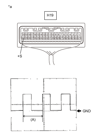
Text in Illustration *a Component with harness connected
(Combination Meter Assembly)
Check the output waveform.
-
Remove the combination meter assembly with the connector still connected.
-
Connect an oscilloscope to terminal H19-40 (+S) and body ground.
-
Turn the power switch on (IG).
-
Check the signal waveform according to the condition(s) in the table below.
Item Condition Tool setting 5 V/DIV., 20 ms./DIV. Vehicle condition Driving at approx. 20 km/h (12 mph) OK The waveform is displayed as shown in the illustration. Tech Tips
When the system is functioning normally, one wheel revolution generates 4 pulses. As the vehicle speed increases, the width indicated by (A) in the illustration narrows.
-
OK
PROCEED TO NEXT SUSPECTED AREA SHOWN IN PROBLEM SYMPTOMS TABLE Click here
NG
REPLACE COMBINATION METER ASSEMBLY Click here
-