LIGHTING SYSTEM Daytime Running Light Relay Circuit
DESCRIPTION
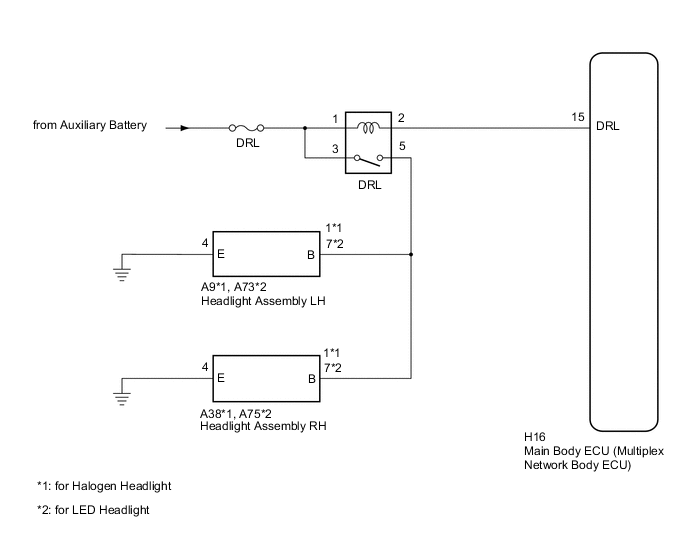
The main body ECU (multiplex network body ECU) controls the daytime running lights.
The system illuminates the high-intensity LED clearance lights (high-intensity circuit).
WIRING DIAGRAM
CAUTION / NOTICE / HINT
Note
Inspect the fuse for circuits related to this system before performing the following procedure.
PROCEDURE
-
PERFORM ACTIVE TEST USING GTS
-
Connect the GTS to the DLC3.
-
Turn the power switch on (IG).
-
Turn the GTS on.
-
Enter the following menus: Body Electrical / Main Body / Active Test.
-
Perform the Active Test according to the display on the GTS.
Main Body Tester Display Test Part Control Range Diagnostic Note Daytime Running Light Daytime running lights OFF or ON - OK Daytime running lights illuminate. (LED clearance lights illuminate on high-intensity (bright) setting.)
OK 
PROCEED TO NEXT SUSPECTED AREA SHOWN IN PROBLEM SYMPTOMS TABLE Click here
NG 
-
-
INSPECT DRL RELAY
-
Inspect the DRL relay.
NG
REPLACE DRL RELAY
OK
-
-
CHECK HARNESS AND CONNECTOR (POWER SOURCE - DRL RELAY)
-
Measure the voltage according to the value(s) in the table below.
Standard Voltage Tester Connection Condition Specified Condition 1 (DRL relay) - Body ground Power switch off 11 to 14 V 3 (DRL relay) - Body ground Power switch off 11 to 14 V
NG
REPAIR OR REPLACE HARNESS OR CONNECTOR
OK
-
-
CHECK HARNESS AND CONNECTOR (DRL RELAY - HEADLIGHT ASSEMBLY LH AND HEADLIGHT ASSEMBLY RH)
-
Disconnect the A9*1 or A73*2 headlight assembly LH connector.
-
Disconnect the A38*1 or A75*2 headlight assembly RH connector.
-
*1: for Halogen Headlight
-
*2: for LED Headlight
-
-
Measure the resistance according to the value(s) in the table below.
Standard Resistance for Halogen Headlight Tester Connection Condition Specified Condition 5 (DRL relay) - A9-1 (B) Always Below 1 Ω 5 (DRL relay) - A38-1 (B) Always Below 1 Ω 5 (DRL relay) or A9-1 (B) - Body ground Always 10 kΩ or higher 5 (DRL relay) or A38-1 (B) - Body ground Always 10 kΩ or higher for LED Headlight Tester Connection Condition Specified Condition 5 (DRL relay) - A73-7 (B) Always Below 1 Ω 5 (DRL relay) - A75-7 (B) Always Below 1 Ω 5 (DRL relay) or A73-7 (B) - Body ground Always 10 kΩ or higher 5 (DRL relay) or A75-7 (B) - Body ground Always 10 kΩ or higher
NG
REPAIR OR REPLACE HARNESS OR CONNECTOR
OK
-
-
CHECK HARNESS AND CONNECTOR (DRL RELAY - MAIN BODY ECU (MULTIPLEX NETWORK BODY ECU))
-
Disconnect the H16 main body ECU (multiplex network body ECU) connector.
-
Measure the resistance according to the value(s) in the table below.
Standard Resistance Tester Connection Condition Specified Condition 2 (DRL relay) - H16-15 (DRL) Always Below 1 Ω 2 (DRL relay) or H16-15 (DRL) - Body ground Always 10 kΩ or higher
OK
REPLACE MAIN BODY ECU (MULTIPLEX NETWORK BODY ECU) Click here
NG
REPAIR OR REPLACE HARNESS OR CONNECTOR
-