LIGHTING SYSTEM, Diagnostic DTC:B124E
| DTC Code | DTC Name |
|---|---|
| B124E | Flasher Relay Circuit |
DESCRIPTION
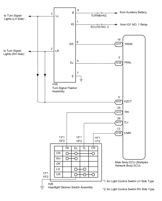
This DTC is stored when the main body ECU (multiplex network body ECU) detects a malfunction in the turn signal flasher relay circuit.
| DTC No. | DTC Detection Condition | Trouble Area |
|---|---|---|
| B124E | Malfunction in turn signal flasher relay circuit |
|
WIRING DIAGRAM
CAUTION / NOTICE / HINT
Note
Inspect the fuses for circuits related to this system before performing the following inspection procedure.
PROCEDURE
-
CLEAR DTC
-
Clear the DTCs Click here.
NEXT 
-
-
CHECK DTC
-
Operate the turn signal switch to cause the left and right turn signal lights to blink for 3 seconds or more.
-
Check for DTCs Click here.
OK DTC B124E is not output.
OK 
USE SIMULATION METHOD TO CHECK Click here
NG
-
-
READ VALUE USING INTELLIGENT TESTER
-
Connect the intelligent tester to the DLC3.
-
Turn the power switch on (IG).
-
Turn the intelligent tester on.
-
Enter the following menus: Body / Main Body / Data List.
-
Read the Data List according to the display on the intelligent tester.
Main Body Tester Display Measurement Item/Range Normal Condition Diagnostic Note Right LaneChgFlas Turn Signal Switch Turn signal switch right turn position signal/ON or OFF ON: Turn signal switch in right turn position
OFF: Turn signal switch in neutral position
- Left LaneChgFlas Turn Signal Switch Turn signal switch left turn position signal/ON or OFF ON: Turn signal switch in left turn position
OFF: Turn signal switch in neutral position
- R or L TurnFlas Turn Signal Switch (Auto Off) Turn signal switch in full turn position signal/ON or OFF ON: Turn signal switch in full left turn or full right turn position
OFF: Turn signal switch in neutral, half left turn or half right turn position
- OK Normal conditions listed above are displayed.
NG 
INSPECT HEADLIGHT DIMMER SWITCH ASSEMBLY (TURN SIGNAL SWITCH) Click here
OK
-
-
INSPECT TURN SIGNAL FLASHER ASSEMBLY
-
Remove the turn signal flasher assembly Click here.
-
Inspect the turn signal flasher assembly Click here.
NG
REPLACE TURN SIGNAL FLASHER ASSEMBLY Click here
OK
-
-
CHECK HARNESS AND CONNECTOR (TURN SIGNAL FLASHER ASSEMBLY - BATTERY AND IG SIGNAL CIRCUIT)
-
Measure the voltage according to the value(s) in the table below.
Standard Voltage Tester Connection Condition Specified Condition H35-4 (B) - Body ground Power switch off 11 to 14 V H35-1 (IG) - Body ground Power switch on (IG) 11 to 14 V -
Measure the resistance according to the value(s) in the table below.
Standard Resistance Tester Connection Condition Specified Condition H35-7 (E) - Body ground Always Below 1 Ω
NG
REPAIR OR REPLACE HARNESS OR CONNECTOR
OK
-
-
CHECK HARNESS AND CONNECTOR (TURN SIGNAL FLASHER ASSEMBLY - MAIN BODY ECU (MULTIPLEX NETWORK BODY ECU)
-
Disconnect the H17 and H18 main body ECU (multiplex network body ECU) connectors.
-
Measure the resistance according to the value(s) in the table below.
Standard Resistance Tester Connection Condition Specified Condition H35-6 (ER) - H17-16 (TRNR) Always Below 1 Ω H35-5 (EL) - H18-5 (TRNL) Always Below 1 Ω H35-6 (ER) - Body ground Always 10 kΩ higher H35-5 (EL) - Body ground Always 10 kΩ higher
NG
REPAIR OR REPLACE HARNESS OR CONNECTOR
OK
-
-
INSPECT TERMINAL VOLTAGE (TURN SIGNAL OUTPUT SIGNAL)
-
Install the turn signal flasher assembly Click here.
-
Reconnect the H17 and H18 main body ECU (multiplex network body ECU) connectors.
-
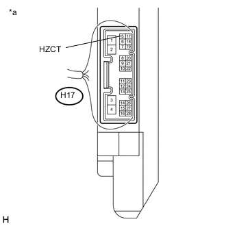
Text in Illustration *a Component with harness connected
(Main Body ECU (Multiplex Network Body ECU))
Measure the voltage according to the value(s) in the table below.
Standard Voltage Tester Connection Condition Specified Condition H17-5 (HZCT) - Body ground Power switch on (IG), turn signal switch in right turn position Below 1 V ←→ 11 to 14 V (60 to 120 times per minute) H17-5 (HZCT) - Body ground Power switch on (IG), turn signal switch in left turn position Below 1 V ←→ 11 to 14 V (60 to 120 times per minute)
OK
REPLACE MAIN BODY ECU (MULTIPLEX NETWORK BODY ECU) Click here
NG
REPAIR OR REPLACE HARNESS OR CONNECTOR
-
-
INSPECT HEADLIGHT DIMMER SWITCH ASSEMBLY (TURN SIGNAL SWITCH)
-
for Light Control Switch LH Side Type:
-
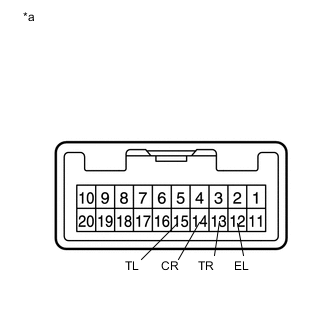
Text in Illustration *a Component without harness connected
(Headlight Dimmer Switch Assembly)
Remove the headlight dimmer switch assembly Click here.
-
Measure the resistance according to the value(s) in the table below.
Standard Resistance Tester Connection Condition Specified Condition 13 (TR) - 12 (EL) Turn signal switch in right turn position Below 1 Ω Turn signal switch in neutral position 10 kΩ or higher 14 (CR) - 12 (EL) Turn signal switch in full right turn position Below 1 Ω Turn signal switch in full left turn position Below 1 Ω Turn signal switch in neutral position 10 kΩ or higher Turn signal switch in half right turn position 10 kΩ or higher Turn signal switch in half left turn position 10 kΩ or higher 15 (TL) - 12 (EL) Turn signal switch in left turn position Below 1 Ω Turn signal switch in neutral position 10 kΩ or higher
-
-
for Light Control Switch RH Side Type:
-
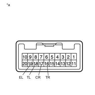
Text in Illustration *a Component without harness connected
(Headlight Dimmer Switch Assembly)
Remove the headlight dimmer switch assembly Click here.
-
Measure the resistance according to the value(s) in the table below.
Standard Resistance Tester Connection Condition Specified Condition 16 (TR) - 19 (EL) Turn signal switch in right turn position Below 1 Ω Turn signal switch in neutral position 10 kΩ or higher 17 (CR) - 19 (EL) Turn signal switch in full right turn position Below 1 Ω Turn signal switch in full left turn position Below 1 Ω Turn signal switch in neutral position 10 kΩ or higher Turn signal switch in half right turn position 10 kΩ or higher Turn signal switch in half left turn position 10 kΩ or higher 18 (TL) - 19 (EL) Turn signal switch in left turn position Below 1 Ω Turn signal switch in neutral position 10 kΩ or higher
-
NG
REPLACE HEADLIGHT DIMMER SWITCH ASSEMBLY Click here
OK
-
-
CHECK HARNESS AND CONNECTOR (HEADLIGHT DIMMER SWITCH ASSEMBLY - MAIN BODY ECU (MULTIPLEX NETWORK BODY) AND BODY GROUND)
-
Disconnect the H26 headlight dimmer switch assembly connector.
-
Disconnect the H17 and H18 main body ECU (multiplex network body ECU) connectors.
-
Measure the resistance according to the value(s) in the table below.
Standard Resistance for Light Control Switch LH Side Type Tester Connection Condition Specified Condition H17-25 (TRI) - H26-13 (TR) Always Below 1 Ω H17-26 (TLI) - H26-15 (TL) Always Below 1 Ω H18-13 (CNRI) - H26-14 (CR) Always Below 1 Ω H26-12 (EL) - Body ground Always Below 1 Ω H17-25 (TRI) - Body ground Always 10 kΩ or higher H17-26 (TLI) - Body ground Always 10 kΩ or higher H18-13 (CNRI) - Body ground Always 10 kΩ or higher for Light Control Switch RH Side Type Tester Connection Condition Specified Condition H17-25 (TRI) - H26-16 (TR) Always Below 1 Ω H17-26 (TLI) - H26-18 (TL) Always Below 1 Ω H18-13 (CNRI) - H26-17 (CR) Always Below 1 Ω H26-19 (EL) - Body ground Always Below 1 Ω H17-25 (TRI) - Body ground Always 10 kΩ or higher H17-26 (TLI) - Body ground Always 10 kΩ or higher H18-13 (CNRI) - Body ground Always 10 kΩ or higher
OK
REPLACE MAIN BODY ECU (MULTIPLEX NETWORK BODY ECU) Click here
NG
REPAIR OR REPLACE HARNESS OR CONNECTOR
-