WIPER SWITCH INSPECTION
PROCEDURE
-
INSPECT WINDSHIELD WIPER SWITCH ASSEMBLY (w/o Rain Sensor)
-
LHD, RHD Light Control Switch LH Side Type:
-
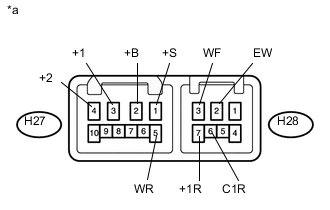
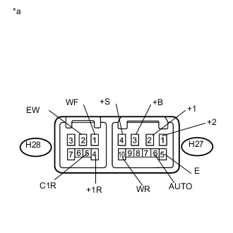
Text in Illustration *a Component without harness connected
(Windshield Wiper Switch Assembly)
Measure the resistance according to the value(s) in the table below.
Standard Resistance Front Wiper Switch Tester Connection Switch Condition Specified Condition H27-1 (+S) - H27-3 (+1) OFF Below 1 Ω INT H27-2 (+B) - H27-3 (+1) MIST LO H27-2 (+B) - H27-4 (+2) HI Front Washer Switch Tester Connection Switch Condition Specified Condition H28-2 (EW) - H28-3 (WF) ON Below 1 Ω OFF 10 kΩ or higher Rear Wiper Switch Tester Connection Switch Condition Specified Condition H28-6 (C1R) - H28-2 (EW) OFF 10 kΩ or higher H28-7 (+1R) - H28-2 (EW) H28-6 (C1R) - H28-2 (EW) INT Below 1 Ω H28-7 (+1R) - H28-2 (EW) HI Below 1 Ω Rear Washer Switch Tester Connection Switch Condition Specified Condition H27-5 (WR) - H28-2 (EW) OFF 10 kΩ or higher H28-7 (+1R) - H28-2 (EW) H27-5 (WR) - H28-2 (EW) WASH Below 1 Ω H27-5 (WR) - H28-2 (EW) ON + WASH Below 1 Ω H28-7 (+1R) - H28-2 (EW) If the result is not as specified, replace the windshield wiper switch assembly.
-
Check the intermittent operation.
-
Connect a voltmeter positive (+) lead to terminal H27-3 (+1) and a negative (-) lead to terminal H28-2 (EW).
-
Connect an auxiliary battery positive (+) lead to terminal H27-2 (+B) and a negative (-) lead to terminal H28-2 (EW) and H27-1 (+S).
-
Turn the wiper switch to the INT position.
-
Connect an auxiliary battery positive (+) lead to terminal H27-1 (+S) for 5 seconds.
-
Connect an auxiliary battery negative (-) lead to terminal H27-1 (+S). Operate the intermittent wiper relay and check the voltage between terminals H27-3 (+1) and H28-2 (EW).
OK Voltage changes as shown in the illustration. 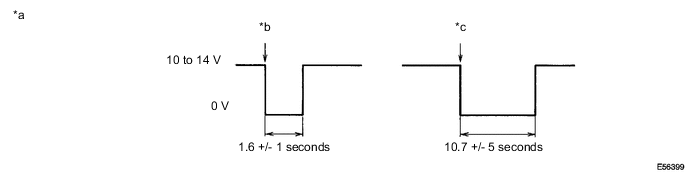
If the result is not as specified, replace the windshield wiper switch assembly.
Text in Illustration *a Voltage between terminals H27-3 (+1) and H28-2 (EW) *b FAST: Connect auxiliary battery negative lead to terminal H27-1 (+S) *c SLOW: Connect auxiliary battery negative lead to terminal H27-1 (+S) - -
-
-
-
RHD Light Control Switch RH Side Type:
-
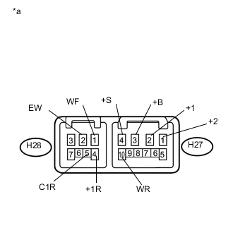
Text in Illustration *a Component without harness connected
(Windshield Wiper Switch Assembly)
Measure the resistance according to the value(s) in the table below.
Standard Resistance Front Wiper Switch Tester Connection Switch Condition Specified Condition H27-4 (+S) - H27-2 (+1) OFF Below 1 Ω INT H27-3 (+B) - H27-2 (+1) MIST LO H27-3 (+B) - H27-1 (+2) HI Front Washer Switch Tester Connection Switch Condition Specified Condition H28-2 (EW) - H28-1 (WF) ON Below 1 Ω OFF 10 kΩ or higher Rear Wiper Switch Tester Connection Switch Condition Specified Condition H28-5 (C1R) - H28-2 (EW) OFF 10 kΩ or higher H28-4 (+1R) - H28-2 (EW) H28-5 (C1R) - H28-2 (EW) INT Below 1 Ω H28-4 (+1R) - H28-2 (EW) HI Below 1 Ω Rear Washer Switch Tester Connection Switch Condition Specified Condition H27-10 (WR) - H28-2 (EW) OFF 10 kΩ or higher H28-4 (+1R) - H28-2 (EW) H27-10 (WR) - H28-2 (EW) WASH Below 1 Ω H27-10 (WR) - H28-2 (EW) ON + WASH Below 1 Ω H28-4 (+1R) - H28-2 (EW) If the result is not as specified, replace the windshield wiper switch assembly.
-
Check the intermittent operation.
-
Connect a voltmeter positive (+) lead to terminal H27-2 (+1) and a negative (-) lead to terminal H28-2 (EW).
-
Connect an auxiliary battery positive (+) lead to terminal H27-3 (+B) and a negative (-) lead to terminal H28-2 (EW) and H27-4 (+S).
-
Turn the wiper switch to the INT position.
-
Connect an auxiliary battery positive (+) lead to terminal H27-4 (+S) for 5 seconds.
-
Connect an auxiliary battery negative (-) lead to terminal H27-4 (+S). Operate the intermittent wiper relay and check the voltage between terminals H27-2 (+1) and H28-2 (EW).
OK Voltage changes as shown in the illustration.
If the result is not as specified, replace the windshield wiper switch assembly.
Text in Illustration *a Voltage between terminals H27-2 (+1) and H28-2 (EW) *b FAST: Connect auxiliary battery negative lead to terminal H27-4 (+S) *c SLOW: Connect auxiliary battery negative lead to terminal H27-4 (+S) - -
-
-
-
-
INSPECT WINDSHIELD WIPER SWITCH ASSEMBLY (w/ Rain Sensor)
-
LHD, RHD Light Control Switch LH Side Type:
-
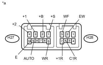
Text in Illustration *a Component without harness connected
(Windshield Wiper Switch Assembly)
Measure the resistance according to the value(s) in the table below.
Standard Resistance Front Wiper Switch Tester Connection Switch Condition Specified Condition H27-1 (+S) - H27-3 (+1) OFF Below 1 Ω AUTO H27-2 (+B) - H27-3 (+1) MIST LO H27-2 (+B) - H27-4 (+2) HI H27-9 (AUTO) - H27-10 (E) AUTO Below 1 Ω Front Washer Switch Tester Connection Switch Condition Specified Condition H28-2 (EW) - H28-3 (WF) ON Below 1 Ω OFF 10 kΩ or higher Rear Wiper Switch Tester Connection Switch Condition Specified Condition H28-6 (C1R) - H28-2 (EW) OFF 10 kΩ or higher H28-7 (+1R) - H28-2 (EW) H28-6 (C1R) - H28-2 (EW) INT Below 1 Ω H28-7 (+1R) - H28-2 (EW) HI Below 1 Ω Rear Washer Switch Tester Connection Switch Condition Specified Condition H27-5 (WR) - H28-2 (EW) OFF 10 kΩ or higher H28-7 (+1R) - H28-2 (EW) H27-5 (WR) - H28-2 (EW) WASH Below 1 Ω H27-5 (WR) - H28-2 (EW) ON + WASH Below 1 Ω H28-7 (+1R) - H28-2 (EW) If the result is not as specified, replace the windshield wiper switch assembly.
-
-
RHD Light Control Switch RH Side Type:
-
Text in Illustration *a Component without harness connected
(Windshield Wiper Switch Assembly)
Measure the resistance according to the value(s) in the table below.
Standard Resistance Front Wiper Switch Tester Connection Switch Condition Specified Condition H27-4 (+S) - H27-2 (+1) OFF Below 1 Ω AUTO H27-3 (+B) - H27-2 (+1) MIST LO H27-3 (+B) - H27-1 (+2) HI H27-6 (AUTO) - H27-5 (E) AUTO Below 1 Ω Front Washer Switch Tester Connection Switch Condition Specified Condition H28-2 (EW) - H28-1 (WF) ON Below 1 Ω OFF 10 kΩ or higher Rear Wiper Switch Tester Connection Switch Condition Specified Condition H28-5 (C1R) - H28-2 (EW) OFF 10 kΩ or higher H28-4 (+1R) - H28-2 (EW) H28-5 (C1R) - H28-2 (EW) INT Below 1 Ω H28-4 (+1R) - H28-2 (EW) HI Below 1 Ω Rear Washer Switch Tester Connection Switch Condition Specified Condition H27-10 (WR) - H28-2 (EW) OFF 10 kΩ or higher H28-4 (+1R) - H28-2 (EW) H27-10 (WR) - H28-2 (EW) WASH Below 1 Ω H27-10 (WR) - H28-2 (EW) ON + WASH Below 1 Ω H28-4 (+1R) - H28-2 (EW) If the result is not as specified, replace the windshield wiper switch assembly.
-
-