POWER MIRROR CONTROL SYSTEM(w/ Memory) Mirror Heater does not Operate with Rear Defogger Switch
DESCRIPTION
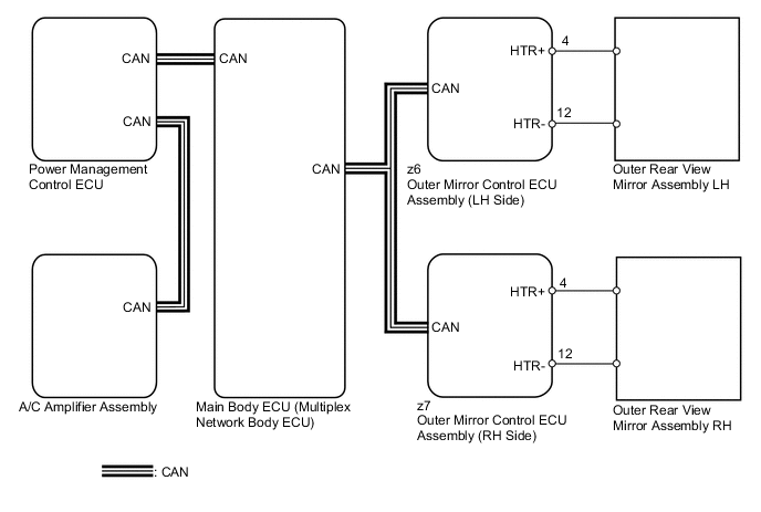
When the rear defogger switch is operated, the mirror heater signal is sent to the A/C amplifier assembly and then to each outer mirror control ECU assembly via CAN communication. Based on the signal, each outer mirror control ECU assembly operates the mirror heater.
WIRING DIAGRAM
CAUTION / NOTICE / HINT
Note
-
The power mirror control system is a part of the CAN communication system. This system features shared communication wiring that reduces the wiring complexity of the communication lines. The first step in any repair is to confirm the proper operation of the communication system. Proceed with troubleshooting after the communication has been verified (See CAN Communication System, Click here.
-
The mirror heater operation is linked with the defogger system or wiper and washer system. Confirm that these systems are operating normally before starting the inspection.
PROCEDURE
-
CHECK WINDOW DEFOGGER SYSTEM
-
Check window defogger system operation Click here.
OK Window defogger system is normal.
NG 
GO TO WINDOW DEFOGGER SYSTEM Click here
OK 
-
-
PERFORM ACTIVE TEST USING INTELLIGENT TESTER
-
Connect the intelligent tester to the DLC3.
-
Turn the power switch on (IG).
-
Turn the intelligent tester on.
-
Enter the following menus: Body / Mirror L or Mirror R / Active Test.
-
Perform an Active Test according to the display on the intelligent tester.
Mirror L / Mirror R Tester Display Test Part Control Range Diagnostic Note Mirror Heater Mirror heater operation ON / OFF
-
Operate with power switch on (IG) and the vehicle stopped.
-
This test activates the mirror heater on or off.
-
Mirror heater operation can be confirmed by touch.
Result Result Proceed to Mirror heater operation on both mirrors are not normal A Mirror heater operation on RH side mirror is not normal B Mirror heater operation on LH side mirror is not normal C -
A
REPLACE A/C AMPLIFIER ASSEMBLY Click here
C 
INSPECT OUTER REAR VIEW MIRROR ASSEMBLY LH Click here
B
-
-
INSPECT OUTER REAR VIEW MIRROR ASSEMBLY RH
-
Text in Illustration *a Component without harness connected
(Outer Rear View Mirror Assembly RH)
Remove the outer rear view mirror assembly RH Click here.
-
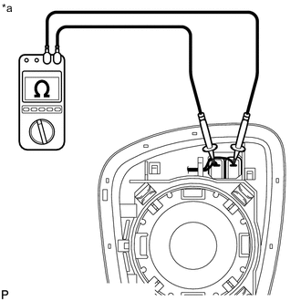
Measure the resistance according to the value(s) in the table below.
Standard Resistance Tester Connection Condition Specified Condition z7-4 (HTR+) - z7-12 (HTR-) 25°C (77°F) 2.4 to 4.4 Ω
OK
REPLACE OUTER MIRROR CONTROL ECU ASSEMBLY (FRONT PASSENGER SIDE) Click here
NG
-
-
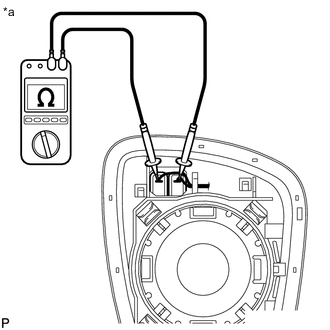
INSPECT OUTER MIRROR RH
-
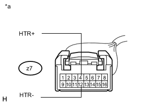
Text in Illustration *a Component without harness connected
(Outer Mirror RH)
Remove the outer mirror RH Click here.
-
Measure the resistance according to the value(s) in the table below.
Standard Resistance Tester Connection Condition Specified Condition 1 - 2 25°C (77°F) 2.4 to 4.4 Ω
OK
REPLACE OUTER MIRROR ACTUATOR ASSEMBLY RH Click here
NG
REPLACE OUTER MIRROR RH Click here
-
-
INSPECT OUTER REAR VIEW MIRROR ASSEMBLY LH
-
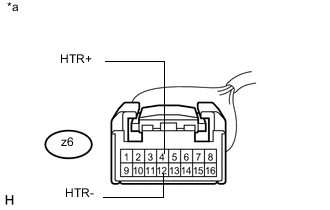
Text in Illustration *a Component without harness connected
(Outer Rear View Mirror Assembly LH)
Remove the outer rear view mirror assembly LH Click here.
-
Measure the resistance according to the value(s) in the table below.
Standard Resistance Tester Connection Condition Specified Condition z6-4 (HTR+) - z6-12 (HTR-) 25°C (77°F) 2.4 to 4.4 Ω
OK
REPLACE OUTER MIRROR CONTROL ECU ASSEMBLY (DRIVER SIDE) Click here
NG
-
-
INSPECT OUTER MIRROR LH
-
Text in Illustration *a Component without harness connected
(Outer Mirror LH)
Remove the outer mirror LH Click here.
-
Measure the resistance according to the value(s) in the table below.
Standard Resistance Tester Connection Condition Specified Condition 1 - 2 25°C (77°F) 2.4 to 4.4 Ω
OK
REPLACE OUTER MIRROR ACTUATOR ASSEMBLY LH Click here
NG
REPLACE OUTER MIRROR LH Click here
-