REAR DOOR ADJUSTMENT

CAUTION / NOTICE / HINT
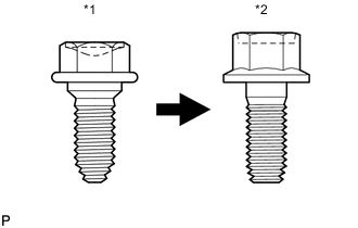
| *1 | Centering Bolt |
| *2 | Standard Bolt |
CAUTION:
Before adjusting the door positions of vehicles equipped with side and curtain shield airbags, be sure to disconnect the battery. After adjustment, check that the SRS warning light is operating normally and there are no SRS DTCs output.
Tech Tips
-
Use the same procedure for the RH side and LH side.
-
The procedure listed below is for the LH side.
-
Centering bolts are used to mount the door hinge to the vehicle body and door. The door cannot be adjusted with the centering bolts installed. Substitute the centering bolts with standard bolts when making adjustments.
-
Specified torque for standard bolts is shown in the standard bolt chart Click here.
PROCEDURE
-
INSPECT REAR DOOR
-
Check that the clearance measurements of areas *a through *r are within each standard range.
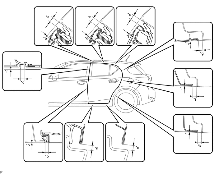
Standard Clearance Area Measurement Area Measurement *a 3.35 to 6.35 mm (0.132 to 0.250 in.) *b 1.5 to 4.5 mm (0.0591 to 0.177 in.) *c 3.35 to 6.35 mm (0.132 to 0.250 in.) *d 1.5 to 4.5 mm (0.0591 to 0.177 in.) *e 3.35 to 6.35 mm (0.132 to 0.250 in.) *f 0.8 to 3.8 mm (0.0315 to 0.150 in.) *g 2.5 to 5.5 mm (0.0984 to 0.217 in.) *h -1.5 to 1.5 mm (-0.0591 to 0.0591 in.) *i 2.5 to 5.5 mm (0.0984 to 0.217 in.) *j -1.5 to 1.5 mm (-0.0591 to 0.0591 in.) *k 2.5 to 5.5 mm (0.0984 to 0.217 in.) *l -1.5 to 1.5 mm (-0.0591 to 0.0591 in.) *m 3.65 to 6.65 mm (0.144 to 0.262 in.) *n 3.65 to 6.65 mm (0.144 to 0.262 in.) *o 2.7 to 5.7 mm (0.106 to 0.224 in.) *p -1.5 to 1.5 mm (-0.0591 to 0.0591 in.) *q 3.0 to 6.0 mm (0.118 to 0.236 in.) *r -1.5 to 1.5 mm (-0.0591 to 0.0591 in.)
-
-
ADJUST REAR DOOR
Note
Make sure that the power switch is off or on (ACC) when adjusting door lock strikers.
-
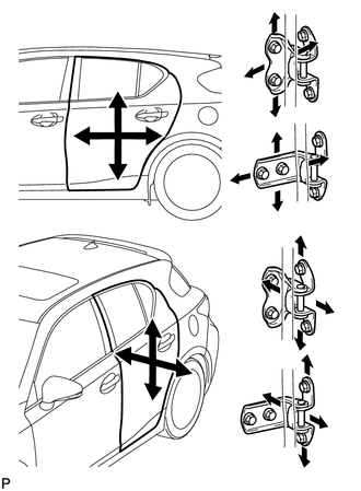
Using SST, loosen the hinge bolts on the vehicle body and adjust the door position.
- SST
- 09812-00010
-
Tighten the hinge bolts on the vehicle body after the adjustment.
- Torque:
- 26 N*m { 265 kgf*cm, 19 ft.*lbf }
-
Loosen the hinge bolts on the door and adjust the door position.
-
Tighten the hinge bolts on the door after the adjustment.
- Torque:
- 27 N*m { 275 kgf*cm, 20 ft.*lbf }
-
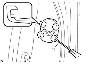
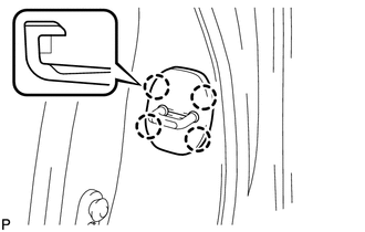
Text in Illustration *1 Protective Tape Using a screwdriver, disengage the 4 claws and remove door lock striker cover.
Tech Tips
Tape the screwdriver tip before use.
-
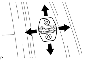
Using a T40 "TORX" socket wrench, slightly loosen the striker mounting screws.
-
Using a brass bar and a hammer, hit the striker to adjust its position.
-
Using a T40 "TORX" socket wrench, tighten the striker mounting screws after adjustment.
- Torque:
- 23 N*m { 235 kgf*cm, 17 ft.*lbf }
-
Engage the 4 claws and install the door lock striker cover.
-