WINDOW DEFOGGER SYSTEM Rear Window Defogger System does not Operate
DESCRIPTION
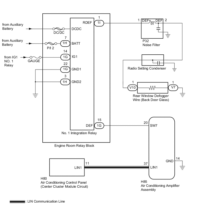
When the rear window defogger switch on the air conditioning control panel is pressed, the operation signal is transmitted to the air conditioning amplifier assembly through a LIN communication line. When the air conditioning amplifier assembly receives the signal, it turns on the No. 1 integration relay to operate the rear window defogger.
WIRING DIAGRAM
CAUTION / NOTICE / HINT
Note
-
Inspect the fuses for circuits related to this system before performing the following inspection procedure.
-
If the auxiliary battery voltage becomes low, rear window defogger operation is canceled to prioritize supplying power to the power steering system.
PROCEDURE
-
CHECK AIR CONDITIONING SYSTEM
-
Check the air conditioning system.
Tech Tips
Both the window defogger system operation signal and air conditioning system operation signal are transmitted to the air conditioning amplifier assembly through the same communication line.
OK The air conditioning system operates normally.
NG 
GO TO AIR CONDITIONING SYSTEM Click here
OK 
-
-
PERFORM ACTIVE TEST USING INTELLIGENT TESTER (DEFOGGER RELAY)
-
Connect the intelligent tester to the DLC3.
-
Turn the power switch on (IG).
-
Turn the intelligent tester on.
-
Enter the following menus: Body / Air Conditioner / Active Test.
-
Perform the Active Test according to the display on the intelligent tester.
Air Conditioner (Air Conditioning Amplifier Assembly) Tester Display Test Part Control Range Diagnostic Note Defogger Relay (Rear) Rear window defogger OFF or ON - OK The rear window defogger system operates normally.
OK
REPLACE AIR CONDITIONING CONTROL PANEL (CENTER CLUSTER MODULE CIRCUIT) Click here
NG
-
-
CHECK HARNESS AND CONNECTOR (NO. 1 INTEGRATION RELAY - AUXILIARY BATTERY AND BODY GROUND)
-
Disconnect the 1G and 1H No. 1 integration relay connectors.
-
Measure the voltage and resistance according to the value(s) in the table below.
Standard Voltage Tester Connection Condition Specified Condition 1H-7 (BATT) - Body ground Power switch off 11 to 14 V 1G-14 (IG1) - Body ground Power switch on (IG) 11 to 14 V 1G-14 (IG1) - Body ground Power switch off Below 1 V Standard Resistance Tester Connection Condition Specified Condition 1G-22 (GND1) - Body ground Always Below 1 Ω 1H-3 (GND2) - Body ground Always Below 1 Ω
NG
REPAIR OR REPLACE HARNESS OR CONNECTOR
OK
-
-
CHECK HARNESS AND CONNECTOR (AIR CONDITIONING AMPLIFIER - NO. 1 INTEGRATION RELAY)
-
Disconnect the H85 air conditioning amplifier assembly connector.
-
Measure the resistance according to the value(s) in the table below.
Standard Resistance Tester Connection Condition Specified Condition H85-20 (SW7) - 1G-15 (DEF) Always Below 1 Ω 1G-15 (DEF) - Body ground Always 10 kΩ or higher H85-14 (GND) - Body ground Always Below 1 Ω
NG
REPAIR OR REPLACE HARNESS OR CONNECTOR
OK
-
-
CHECK NO. 1 INTEGRATION RELAY
-
Reconnect the 1G and 1H No. 1 integration relay connectors.
-
Measure the voltage according to the value(s) in the table below.
Standard Voltage Tester Connection Condition Specified Condition H85-20 (SW7) - Body ground Always 11 to 14 V
NG
REPLACE NO. 1 INTEGRATION RELAY Click here
OK
-
-
CHECK AIR CONDITIONING AMPLIFIER ASSEMBLY
-
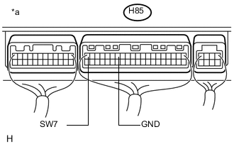
Text in Illustration *a Rear view of wire harness connector
(to Air Conditioning Amplifier Assembly)
Reconnect the H85 air conditioning amplifier assembly connector.
-
Measure the voltage according to the value(s) in the table below.
Standard Voltage Tester Connection Condition Specified Condition H85-20 (SW7) - H85-14 (GND) Power switch on (IG), rear window defogger switch off 11 to 14 V H85-20 (SW7) - H85-14 (GND) Power switch on (IG), rear window defogger switch on Below 1 V
NG
REPLACE AIR CONDITIONING AMPLIFIER ASSEMBLY Click here
OK
-
-
CHECK HARNESS AND CONNECTOR (NO. 1 INTEGRATION RELAY - NOISE FILTER)
-
Disconnect the 1I No. 1 integration relay connector.
-
Disconnect the P32 noise filter connector.
-
Measure the resistance according to the value(s) in the table below.
Standard Resistance Tester Connection Condition Specified Condition 1I-1 (RDEF) - P32-1 (DEF+) Always Below 1 Ω 1I-1 (RDEF) - Body ground Always 10 kΩ or higher P32-1 (DEF+) - Body ground Always 10 kΩ or higher
NG
REPAIR OR REPLACE HARNESS OR CONNECTOR
OK
-
-
CHECK NO. 1 INTEGRATION RELAY
-
Reconnect the 1I No. 1 integration relay connector.
-
Measure the voltage according to the value(s) in the table below.
Standard Voltage Tester Connection Condition Specified Condition P32-1 (DEF+) - Body ground Power switch on (IG), rear window defogger switch on 11 to 14 V P32-1 (DEF+) - Body ground Power switch on (IG), rear window defogger switch off Below 1 V
NG 
REPLACE NO. 1 INTEGRATION RELAY Click here
OK
-
-
INSPECT NOISE FILTER
-
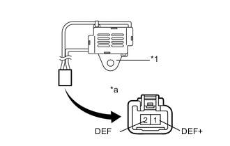
Text in Illustration *1 Body *a Component without harness connected
(Noise Filter)
Remove the noise filter.
-
Measure the resistance according to the value(s) in the table below.
Standard Resistance Tester Connection Condition Specified Condition 1 (DEF+) - 2 (DEF) Always Below 1 Ω 1 (DEF+) - Body ground Always 10 kΩ or higher 2 (DEF) - Body ground Always 10 kΩ or higher
NG
REPLACE NOISE FILTER
OK
-
-
INSPECT RADIO SETTING CONDENSER
-
Remove the radio setting condenser Click here.
-
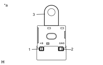
Text in Illustration *a Radio Setting Condenser Measure the resistance of the radio setting condenser according to the value(s) in the table below.
Standard Resistance Tester Connection Condition Specified Condition 1 - 2 Always 10 kΩ or higher 2 - 3 Always Below 1 Ω
NG
REPLACE RADIO SETTING CONDENSER Click here
OK
-
-
CHECK HARNESS AND CONNECTOR (NOISE FILTER - REAR WINDOW DEFOGGER WIRE)
-
Disconnect the V10 rear window defogger wire (back door glass) auxiliary battery side connector.
-
Measure the resistance according to the value(s) in the table below.
Standard Resistance Tester Connection Condition Specified Condition P32-2 (DEF) - V10-1 Always Below 1 Ω P32-2 (DEF) - Body ground Always 10 kΩ or higher V10-1 - Body ground Always 10 kΩ or higher
NG
REPAIR OR REPLACE HARNESS OR CONNECTOR
OK
-
-
CHECK HARNESS AND CONNECTOR (REAR WINDOW DEFOGGER WIRE - BODY GROUND)
-
Disconnect the V7 rear window defogger wire (back door glass) ground side connector.
-
Measure the resistance according to the value(s) in the table below.
Standard Resistance Tester Connection Condition Specified Condition V7-1 - Body ground Always Below 1 Ω
OK
REPAIR OR REPLACE REAR WINDOW DEFOGGER WIRE (BACK DOOR GLASS) Click here
NG
REPAIR OR REPLACE HARNESS OR CONNECTOR
-
-
REPLACE NO. 1 INTEGRATION RELAY
-
Replace the No. 1 integration relay Click here.
NEXT
-
-
CHECK WINDOW DEFOGGER SYSTEM
-
Check the operation of the window defogger system.
OK The rear window defogger system operates normally.
OK
END (NO. 1 INTEGRATION RELAY WAS DEFECTIVE)
NG
REPAIR OR REPLACE HARNESS OR CONNECTOR (POWER SOURCE)
-