ROOF HEADLINING REMOVAL

PROCEDURE
-
REMOVE REAR NO. 2 FLOOR BOARD
-
Remove the rear No. 2 floor board.
-
-
REMOVE REAR DECK FLOOR BOX
-
Remove the rear deck floor box.
-
-
REMOVE REAR NO. 3 FLOOR BOARD
-
Remove the rear No. 3 floor board.
-
-
REMOVE DECK FLOOR BOX RH
-
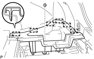
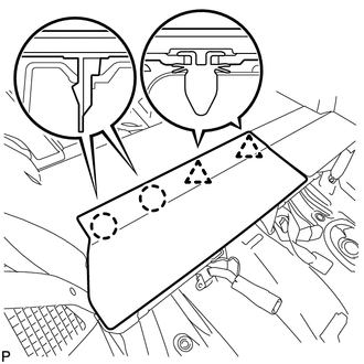
Remove the clip.
-
Disengage the 6 guides and remove the deck floor box RH.
-
-
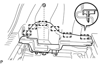
REMOVE REAR FLOOR BOARD UPPER NO. 3 PLATE
-
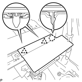
Disengage the 4 claws and 2 guides, and remove the rear floor board upper No. 3 plate.
-
-
REMOVE REAR SEAT ASSEMBLY
-
REMOVE REAR NO. 4 FLOOR BOARD (w/o Woofer)
-
Remove the rear No. 4 floor board.
-
-
REMOVE REAR NO. 4 FLOOR BOARD (w/ Woofer)
-
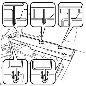
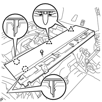
Disengage the 2 clips and 3 guides, and remove the rear No. 4 floor board.
-
-
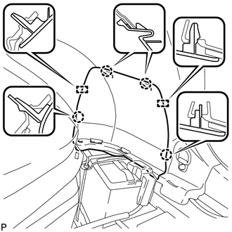
REMOVE DECK FLOOR BOX LH (w/o Woofer)
-
Remove the clip.
-
Disengage the 6 guides and remove the deck floor box LH.
-
-
REMOVE TONNEAU COVER ASSEMBLY (w/ Tonneau Cover)
-
Remove the tonneau cover assembly.
-
-
REMOVE REAR NO. 1 FLOOR BOARD SUB-ASSEMBLY
-
Disengage the 2 claws and 2 clips, and remove the rear No. 1 floor board sub-assembly.
-
-
REMOVE REAR NO. 2 FLOOR BOARD SUB-ASSEMBLY
-
Disengage the claw and 2 clips, and remove the rear No. 2 floor board sub-assembly.
-
-
REMOVE REAR NO. 1 FLOOR BOARD
-
Remove the bolt.
-
Disengage the 2 claws and 2 clips, and remove the rear No. 1 floor board.
-
-
REMOVE DECK TRIM SERVICE HOLE COVER
-
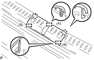
Disengage the 2 claws and guide (A).
-
Disengage the 2 guides (B) and remove the deck trim service hole cover.
-
-
REMOVE REAR DECK TRIM COVER
-
Disengage the 4 clips and remove the rear deck trim cover.
-
-
REMOVE FRONT SEAT ASSEMBLY
Tech Tips
Use the same procedure for the RH side and LH side.
for Manual Seat:
for Power Seat:
-
REMOVE FRONT DOOR SCUFF PLATE LH
-
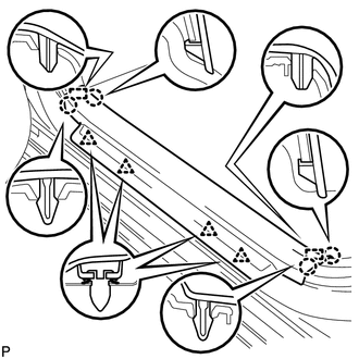
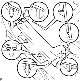
Disengage the 4 claws, 2 guides and 4 clips, and remove the front door scuff plate LH.
-
-
REMOVE NO. 2 INSTRUMENT PANEL UNDER COVER SUB-ASSEMBLY (for RHD)
-
REMOVE COWL SIDE TRIM SUB-ASSEMBLY LH
-
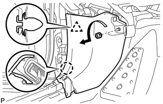
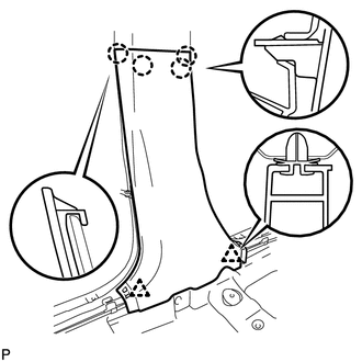
Remove the clip as shown in the illustration.
-
Disengage the clip and claw, and remove the cowl side trim sub-assembly LH.
-
-
REMOVE FRONT DOOR OPENING TRIM WEATHERSTRIP LH
-
Remove the front door opening trim weatherstrip LH.
-
Remove any residual weatherstrip sealant from the vehicle body using cleaner.
Note
Remove the sealant completely. Any residual sealant may transfer to other areas of the vehicle when removing/installing the interior parts.
-
-
REMOVE FRONT PILLAR GARNISH LH
-
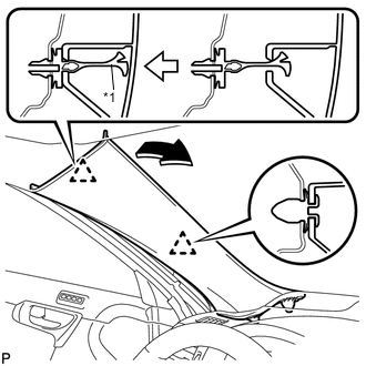
Text in Illustration *1 Front Pillar Garnish Clip Pull the upper part of the garnish toward the inside of the cabin and disengage the 2 clips.
Tech Tips
Make the front pillar garnish LH hang from the front pillar garnish clip.
-
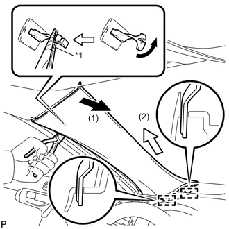
Text in Illustration *1 Protective Tape Turn the end of the front pillar garnish clip 90° with needle-nosed pliers and remove it from the front pillar garnish LH.
Note
-
Front pillar garnish clips are reusable if they are not removed from the vehicle and have no damage.
-
Replace the front pillar garnish clips with new ones if they are removed from the vehicle.
Tech Tips
Tape the tips of the needle-nosed pliers before use.
-
-
Disengage the 2 guides.
-
w/o Front Center Speaker:
-
Remove the front pillar garnish LH by pulling it in the direction indicated by the arrow (2) in the illustration.
-
-
w/ Front Center Speaker:
-
Disconnect the front pillar garnish LH by pulling it in the direction indicated by the arrow (2) in the illustration.
-
Disconnect the connector and remove the front pillar garnish LH.
-
-
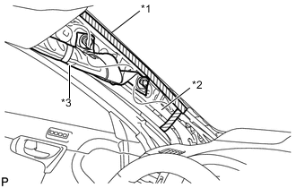
Text in Illustration *1 Adhesive Tape *2 Protective Cover *3 Curtain Shield Airbag Assembly Protect the curtain shield airbag assembly.
-
Cover the airbag with a cloth or piece of nylon and secure the ends of the cover with tape as shown in the illustration.
Note
Cover the curtain shield airbag with a protective cover as soon as the front pillar garnish is removed.
-
-
-
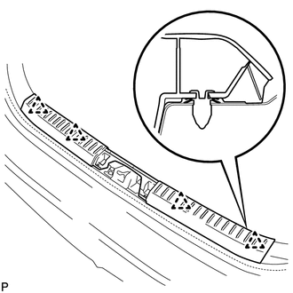
REMOVE REAR DOOR SCUFF PLATE LH
-
Disengage the 4 claws, 2 guides and 2 clips, and remove the rear door scuff plate LH.
-
-
REMOVE REAR DOOR OPENING TRIM WEATHERSTRIP LH
-
Remove the rear door opening trim weatherstrip LH.
-
Remove any residual weatherstrip sealant from the vehicle body using cleaner.
Note
Remove the sealant completely. Any residual sealant may transfer to other areas of the vehicle when removing/installing the interior parts.
-
-
REMOVE LAP BELT OUTER ANCHOR COVER (for LH Side)
-
DISCONNECT FRONT SEAT OUTER BELT ASSEMBLY LH
-
REMOVE CENTER PILLAR LOWER GARNISH LH
-
Disengage the 4 claws and 2 clips, and remove the center pillar lower garnish LH.
-
-
REMOVE CENTER PILLAR UPPER GARNISH LH
-
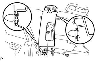
Remove the screw.
-
Disengage the 2 clips.
-
Pass the floor anchor of the front seat outer belt assembly LH through the center pillar upper garnish LH and remove the center pillar upper garnish LH.
-
-
REMOVE FRONT DOOR SCUFF PLATE RH
Tech Tips
Use the same procedure as for the LH side.
-
REMOVE COWL SIDE TRIM SUB-ASSEMBLY RH
Tech Tips
Use the same procedure as for the LH side.
-
REMOVE FRONT DOOR OPENING TRIM WEATHERSTRIP RH
Tech Tips
Use the same procedure as for the LH side.
-
REMOVE FRONT PILLAR GARNISH RH
Tech Tips
Use the same procedure as for the LH side.
-
REMOVE REAR DOOR SCUFF PLATE RH
Tech Tips
Use the same procedure as for the LH side.
-
REMOVE REAR DOOR OPENING TRIM WEATHERSTRIP RH
Tech Tips
Use the same procedure as for the LH side.
-
REMOVE LAP BELT OUTER ANCHOR COVER (for RH Side)
Tech Tips
Use the same procedure as for the LH side.
-
DISCONNECT FRONT SEAT OUTER BELT ASSEMBLY RH
Tech Tips
Use the same procedure as for the LH side.
-
REMOVE CENTER PILLAR LOWER GARNISH RH
Tech Tips
Use the same procedure as for the LH side.
-
REMOVE CENTER PILLAR UPPER GARNISH RH
Tech Tips
Use the same procedure as for the LH side.
-
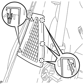
REMOVE REAR SEAT SIDE GARNISH LH
-
Remove the clip.
-
Disengage the 6 claws and remove the rear seat side garnish LH.
-
-
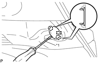
REMOVE ROPE HOOK ASSEMBLY (for LH Side)
-
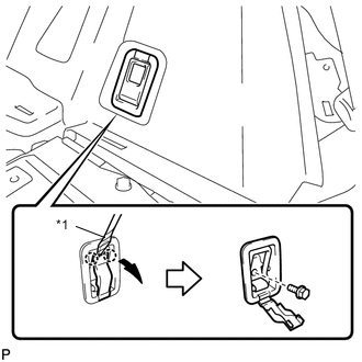
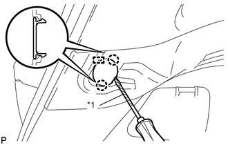
Text in Illustration *1 Protective Tape Using a screwdriver, disengage the 2 claws.
Tech Tips
Tape the screwdriver tip before use.
-
Remove the bolt and the rope hook assembly.
-
-
REMOVE LUGGAGE HOLD BELT STRIKER ASSEMBLY (for LH Side)
-
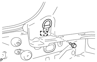
Remove the bolt.
-
Disengage the guide and remove the luggage hold belt striker assembly.
-
-
REMOVE TONNEAU COVER HOOK (for LH Side)
-
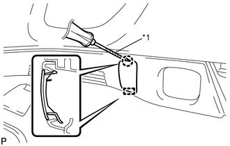
Text in Illustration *1 Protective Tape Using a screwdriver, disengage the 2 claws and pin, and remove the tonneau cover hook.
Tech Tips
Tape the screwdriver tip before use.
-
-
REMOVE TONNEAU COVER HOLDER CAP (for LH Side)
-
Text in Illustration *1 Protective Tape Using a screwdriver, disengage the claws and guide, and remove the tonneau cover holder cap.
Tech Tips
Tape the screwdriver tip before use.
-
-
DISCONNECT REAR SEAT OUTER BELT ASSEMBLY LH
-
REMOVE DECK TRIM SIDE PANEL ASSEMBLY LH
-
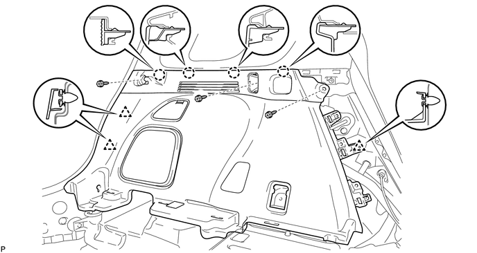
Remove the 3 screws.
-
Disengage the 4 claws and 3 clips, and remove the deck trim side panel assembly LH.
-
-
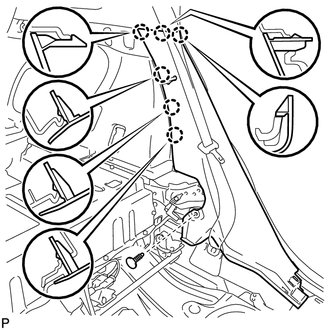
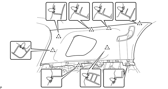
REMOVE ROOF SIDE INNER GARNISH ASSEMBLY LH
-
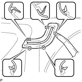
Using a moulding remover, disengage the 3 claws and 2 guides, and disconnect the belt guide.
-
Disengage the 8 clips
-
Pass the floor anchor of the rear seat outer belt assembly LH through the roof side inner garnish assembly LH and remove the roof side inner garnish assembly LH.
-
-
REMOVE REAR SEAT SIDE COVER RH
-
Disengage the 3 claws and 2 clips, and remove the rear seat side cover RH.
-
-
REMOVE REAR SEAT SIDE GARNISH RH
Tech Tips
Use the same procedure as for the LH side.
-
REMOVE ROPE HOOK ASSEMBLY (for RH Side)
Tech Tips
Use the same procedure as for the LH side.
-
REMOVE LUGGAGE HOLD BELT STRIKER ASSEMBLY (for RH Side)
Tech Tips
Use the same procedure as for the LH side.
-
REMOVE TONNEAU COVER HOOK (for RH Side)
-
Text in Illustration *1 Protective Tape Using a screwdriver, disengage the 2 claws and pin, and remove the tonneau cover hook.
Tech Tips
Tape the screwdriver tip before use.
-
-
REMOVE TONNEAU COVER HOLDER CAP (for RH Side)
Tech Tips
Use the same procedure as for the LH side.
-
REMOVE NO. 2 ROOM LIGHT ASSEMBLY
-
DISCONNECT REAR SEAT OUTER BELT ASSEMBLY RH
Tech Tips
Use the same procedure as for the LH side.
-
REMOVE DECK TRIM SIDE PANEL ASSEMBLY RH
Tech Tips
Use the same procedure as for the LH side.
-
REMOVE ROOF SIDE INNER GARNISH ASSEMBLY RH
Tech Tips
Use the same procedure as for the LH side.
-
REMOVE UPPER INSTRUMENT PANEL ASSEMBLY
-
REMOVE BACK DOOR WEATHERSTRIP
-
Remove the back door weatherstrip.
-
Remove any residual weatherstrip sealant from the vehicle body using cleaner.
Note
Remove the sealant completely. Any residual sealant may transfer to other areas of the vehicle when removing/installing the interior parts.
-
-
REMOVE MAP LIGHT ASSEMBLY
-
REMOVE NO. 1 ROOM LIGHT ASSEMBLY
-
REMOVE INNER REAR VIEW MIRROR STAY HOLDER COVER (w/ Cover)
-
REMOVE RAIN SENSOR COVER (w/ Rain Sensor)
w/o Pre-collision System:
w/ Pre-collision System:
-
REMOVE PROTECTOR (w/ Humidity Sensor)
w/o Pre-collision System:
w/ Pre-collision System:
-
REMOVE NO. 2 FORWARD RECOGNITION COVER (w/ Pre-collision System)
-
REMOVE NO. 1 FORWARD RECOGNITION COVER (w/ Pre-collision System)
-
REMOVE ASSIST GRIP SUB-ASSEMBLY
Tech Tips
Use the same procedure for all assist grip sub-assemblies.
-
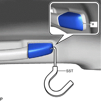
*a Cutout Insert SST into the cutout of the assist grip cover as shown in the illustration.
- SST
- 09813-00010
Note
To prevent the assist grip sub-assembly from being damaged, make sure to insert SST straight into the cutout.
-
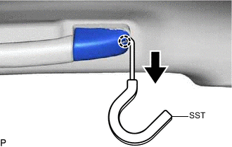

Pull in this Direction Pull SST as shown in the illustration to disengage the claw.
Note
To prevent the assist grip sub-assembly from being damaged, make sure to only pull SST as shown in the illustration.
-
Remove the assist grip cover.
Tech Tips
Use the same procedure for the LH side and RH side.
-
Remove the 2 clips from the vehicle body.
-
-
REMOVE VISOR BRACKET COVER (for LH Side)
-
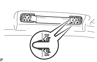
Using a moulding remover, disengage the 4 claws and remove the visor bracket cover LH.
-
-
REMOVE VISOR ASSEMBLY LH
-
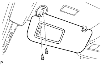
Remove the 2 screws and the visor assembly LH.
-
-
REMOVE VISOR BRACKET COVER (for RH Side)
Tech Tips
Use the same procedure as for the LH side.
-
REMOVE VISOR ASSEMBLY RH
Tech Tips
Use the same procedure as for the LH side.
-
REMOVE SLIDING ROOF OPENING TRIM MOULDING (w/ Sliding Roof)
-
Remove the sliding roof opening trim moulding.
-
-
REMOVE VISOR HOLDER
-
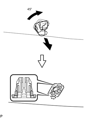
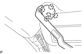
Turn the visor holder approximately 45° and pull it out as shown in the illustration.
-
Disengage the 2 claws and remove the visor holder.
Tech Tips
Use the same procedure for the other visor holder.
-
-
REMOVE ROOF HEADLINING ASSEMBLY (w/o Sliding Roof)
-
for Windshield Glass Side:
-
w/ Humidity Sensor:
-
Disconnect the connector.
-
-
w/ EC Mirror:
-
Disconnect the connector.
-
-
w/ Pre-collision System:
-
Disconnect the 2 connectors.
-
-
w/ Rain Sensor:
-
Disconnect the connector.
-
-
-
for Front Pillar RH Side:
-
w/ Radio Receiver:
-
Remove the protective cover.
-
Disengage the 3 clamps and disconnect each connector.
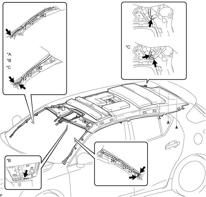
*A w/ Digital Audio Broadcasting Antenna *B w/ Television Antenna Assembly *C w/ Telematics Transceiver - - -
Install the protective cover.
-
-
-
for Front Pillar LH Side:
-
Remove the protective cover.
-
Disengage the 3 clamps and disconnect the 2 connectors.
-
Install the protective cover.
-
-
for Rear Pillar RH Side:
-
Disconnect each connector.
-
-
for Roof Side:
-
w/ Television Antenna Assembly:
-
Disconnect the connector.
-
-
-
Remove the 3 clips.
-
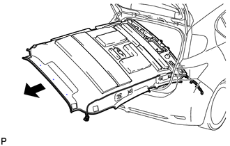
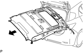
Remove the roof headlining assembly from the vehicle through the back door.
Note
Do not damage the roof headlining assembly or vehicle interior.
-
-
REMOVE ROOF HEADLINING ASSEMBLY (w/ Sliding Roof)
-
for Windshield Glass Side:
-
w/ Humidity Sensor:
-
Disconnect the connector.
-
-
w/ EC Mirror:
-
Disconnect the connector.
-
-
w/ Pre-collision System:
-
Disconnect the 2 connectors.
-
-
w/ Rain Sensor:
-
Disconnect the connector.
-
-
-
for Front Pillar RH Side:
-
w/ Radio Receiver:
-
Remove the protective cover.
-
Disengage the 3 clamps and disconnect each connector.
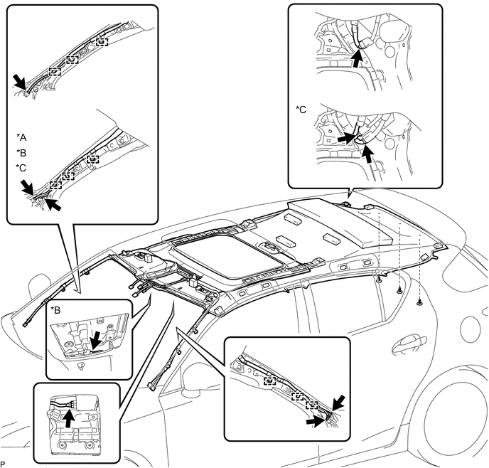
*A w/ Digital Audio Broadcasting Antenna *B w/ Television Antenna Assembly *C w/ Telematics Transceiver - - -
Install the protective cover.
-
-
-
for Front Pillar LH Side:
-
Remove the protective cover.
-
Disengage the 3 clamps and disconnect the 2 connectors.
-
Install the protective cover.
-
-
for Rear Pillar RH Side:
-
Disconnect each connector.
-
-
for Roof Side:
-
Disconnect each connector.
-
-
Remove the 3 clips.
-
Remove the roof headlining assembly from the vehicle through the back door.
Note
Do not damage the roof headlining assembly or vehicle interior.
-