UPPER INSTRUMENT PANEL INSTALLATION
PROCEDURE
-
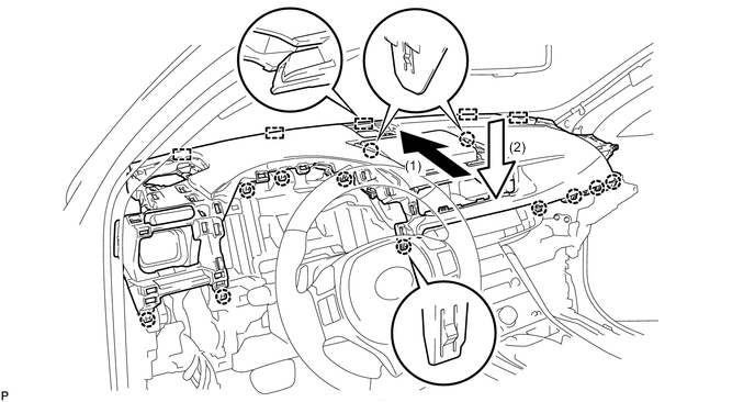
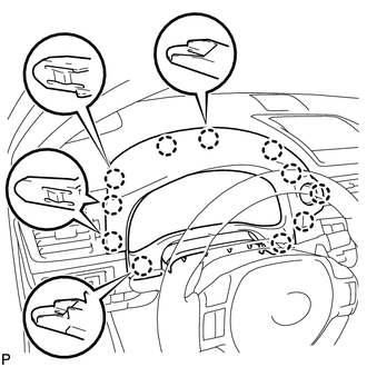
INSTALL UPPER INSTRUMENT PANEL ASSEMBLY
-
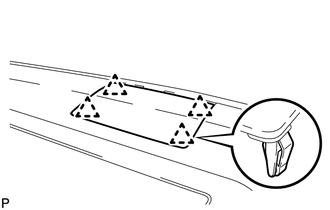
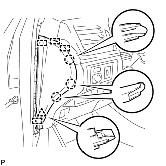
Engage the 5 guides.
Note
Do not damage the upper instrument panel assembly.
-
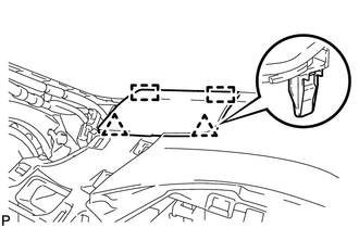
Engage the 12 claws.
-
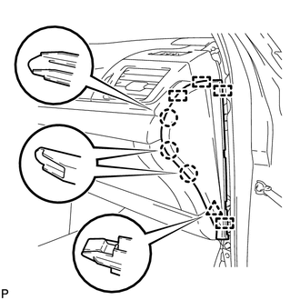
Install the upper instrument panel assembly with the 2 bolts <A> and 2 screws <B>.
- Torque:
- Bolt <A>
- 20 N*m { 204 kgf*cm, 15 ft.*lbf }
-
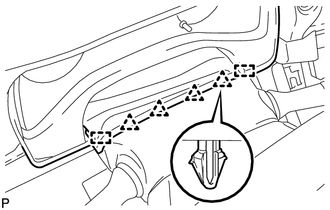
Engage the clamp.
-
Connect each connector.
-
-
CONNECT NO. 3 INSTRUMENT PANEL WIRE
-
INSTALL MULTI-DISPLAY (w/ Navigation System)
-
INSTALL INSTRUMENT CLUSTER FINISH PANEL SUB-ASSEMBLY (w/ Navigation System)
-
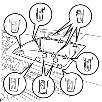
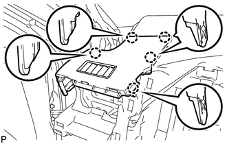
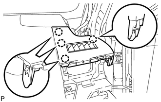
Engage the 5 claws and 6 clips to install the instrument cluster finish panel sub-assembly.
-
-
INSTALL INSTRUMENT CLUSTER FINISH PANEL SUB-ASSEMBLY (w/ Instrument Panel Box)
-
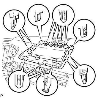
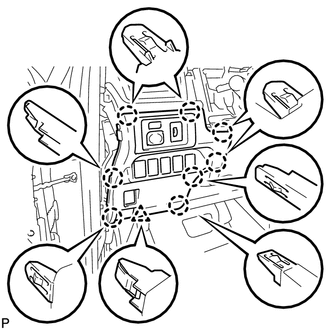
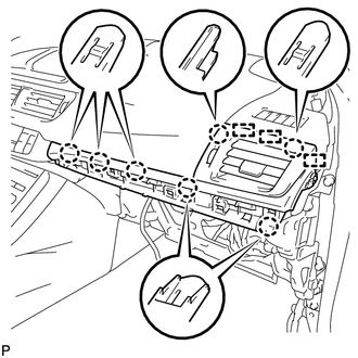
Engage the 16 claws to install the instrument cluster finish panel sub-assembly.
-
-
INSTALL CENTER INSTRUMENT PANEL REGISTER ASSEMBLY
-
Connect the connector.
-
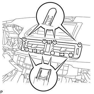
Engage the 3 guides and 8 claws to install the center instrument panel register assembly.
-
-
INSTALL FRONT NO. 4 SPEAKER ASSEMBLY (w/ Front Center Speaker)
-
INSTALL NO. 1 SPEAKER OPENING COVER ASSEMBLY
-
Engage the 4 clips to install the No. 1 speaker opening cover assembly.
-
-
INSTALL FRONT NO. 2 SPEAKER ASSEMBLY (w/ Front No. 2 Speaker)
-
INSTALL NO. 2 INSTRUMENT PANEL SPEAKER PANEL SUB-ASSEMBLY
-
Engage the 2 guides and 2 clips to install the No. 2 instrument panel speaker panel sub-assembly.
-
-
INSTALL NO. 1 DEFROSTER NOZZLE OPENING PLATE
-
Engage the 5 claws to install the No. 1 defroster nozzle opening plate.
-
-
INSTALL NO. 1 INSTRUMENT PANEL REGISTER ASSEMBLY
-
Engage the 3 guides and 4 claws to install the No. 1 instrument panel register assembly.
-
-
INSTALL FRONT PILLAR GARNISH LH
-
INSTALL LOWER INSTRUMENT PANEL FINISH PANEL SUB-ASSEMBLY
-
Connect each connector.
-
Engage the 8 claws and clip to install the lower instrument panel finish panel sub-assembly.
-
-
INSTALL INSTRUMENT SIDE PANEL LH
-
Engage the 4 guides, clip and 3 claws to install the instrument side panel LH.
-
-
INSTALL FRONT DOOR OPENING TRIM WEATHERSTRIP LH
-
INSTALL FRONT NO. 2 SPEAKER ASSEMBLY (w/ Front No. 2 Speaker)
Tech Tips
Use the same procedure described for the LH side.
-
INSTALL NO. 1 INSTRUMENT PANEL SPEAKER PANEL SUB-ASSEMBLY
Tech Tips
Use the same procedure described for the LH side.
-
INSTALL NO. 2 DEFROSTER NOZZLE OPENING PLATE
-
Engage the 4 claws to install the No. 2 defroster nozzle opening plate.
-
-
INSTALL NO. 2 INSTRUMENT PANEL REGISTER ASSEMBLY
-
Engage the 3 guides and 7 claws to install the No. 2 instrument panel register assembly.
-
-
INSTALL NO. 3 INSTRUMENT CLUSTER FINISH PANEL GARNISH (for Metal Finish Panel and Urethane Panel)
-
Engage the 5 clips to install the No. 3 instrument cluster finish panel garnish.
-
-
INSTALL NO. 3 INSTRUMENT CLUSTER FINISH PANEL GARNISH (for Wood Panel and Bamboo Panel)
-
Engage the 4 clips to install the No. 3 instrument cluster finish panel garnish.
-
-
INSTALL FRONT PILLAR GARNISH RH
Tech Tips
Use the same procedure described for the LH side.
-
INSTALL GLOVE COMPARTMENT DOOR ASSEMBLY
-
Connect the connector.
-
Engage the clamp.
-
Engage the 5 claws.
-
Install the glove compartment door assembly with the 4 screws <C>.
-
-
INSTALL LOWER NO. 2 INSTRUMENT PANEL AIRBAG ASSEMBLY
-
INSTALL COWL SIDE TRIM SUB-ASSEMBLY RH
Tech Tips
Use the same procedure described for the LH side Click here.
-
INSTALL FRONT DOOR SCUFF PLATE RH
Tech Tips
Use the same procedure described for the LH side Click here.
-
INSTALL NO. 2 INSTRUMENT PANEL UNDER COVER SUB-ASSEMBLY (for LHD)
-
Connect the connector.
-
Engage the clamp.
-
Engage the guide, claw and 2 clips to install the No. 2 instrument panel under cover sub-assembly.
-
-
INSTALL NO. 2 INSTRUMENT PANEL UNDER COVER SUB-ASSEMBLY (for RHD)
-
Connect the connector.
-
Engage the clamp.
-
Engage the 2 guides, claw and 2 clips to install the No. 2 instrument panel under cover sub-assembly.
-
-
INSTALL INSTRUMENT SIDE PANEL RH
-
Connect the connector.
-
Engage the 4 guides, clip and 3 claws to install the instrument side panel RH.
-
-
INSTALL FRONT DOOR OPENING TRIM WEATHERSTRIP RH
-
INSTALL COMBINATION METER ASSEMBLY
-
INSTALL METER HOOD SUB-ASSEMBLY
-
Connect the connector.
-
Engage the 11 claws.
-
Engage the 2 guides and 4 clips to install the meter hood sub-assembly.
-
-
CONNECT CABLE TO NEGATIVE BATTERY TERMINAL
Note
When disconnecting the cable, some systems need to be initialized after the cable is reconnected Click here.
-
INSTALL REAR FLOOR BOARD UPPER NO. 3 PLATE
-
INSTALL DECK FLOOR BOX RH
-
INSTALL REAR NO. 3 FLOOR BOARD
-
INSTALL REAR DECK FLOOR BOX
-
INSTALL REAR NO. 2 FLOOR BOARD
-
PERFORM DIAGNOSTIC SYSTEM CHECK
-
INSPECT SRS WARNING LIGHT