UPPER INSTRUMENT PANEL REMOVAL
PROCEDURE
-
PRECAUTION
Note
After turning the power switch off, waiting time may be required before disconnecting the cable from the negative (-) battery terminal. Therefore, make sure to read the disconnecting the cable from the negative (-) battery terminal notices before proceeding with work Click here.
-
REMOVE REAR NO. 2 FLOOR BOARD
-
REMOVE REAR DECK FLOOR BOX
-
REMOVE REAR NO. 3 FLOOR BOARD
-
REMOVE DECK FLOOR BOX RH
-
REMOVE REAR FLOOR BOARD UPPER NO. 3 PLATE
-
DISCONNECT CABLE FROM NEGATIVE BATTERY TERMINAL
Note
When disconnecting the cable, some systems need to be initialized after the cable is reconnected Click here.
-
REMOVE METER HOOD SUB-ASSEMBLY
-
Operate the tilt and telescopic lever to fully extend and lower the steering column assembly.
-
Using a moulding remover, disengage the 4 clips and 2 guides.
-
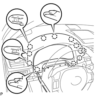
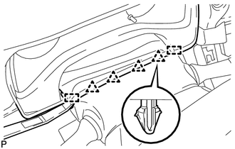
Using a moulding remover, disengage the 11 claws.
-
Disconnect the connector and remove the meter hood sub-assembly.
-
-
REMOVE COMBINATION METER ASSEMBLY
-
DISCONNECT FRONT DOOR OPENING TRIM WEATHERSTRIP LH
-
REMOVE INSTRUMENT SIDE PANEL LH
-
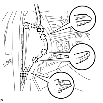
Using a moulding remover, disengage the 3 claws, clip and 4 guides, and remove the instrument side panel LH.
-
-
REMOVE LOWER INSTRUMENT PANEL FINISH PANEL SUB-ASSEMBLY
-
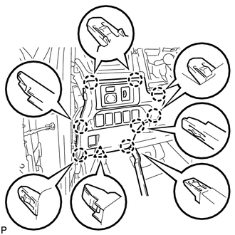
Using a moulding remover, disengage the 8 claws and clip.
-
Disconnect each connector and remove the lower instrument panel finish panel sub-assembly.
-
-
REMOVE FRONT PILLAR GARNISH LH
-
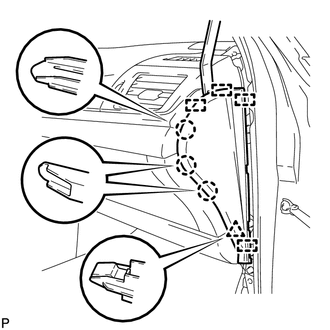
REMOVE NO. 1 INSTRUMENT PANEL REGISTER ASSEMBLY
-
Disengage the 4 claws and 3 guides, and remove the No. 1 instrument panel register assembly.
-
-
REMOVE NO. 1 DEFROSTER NOZZLE OPENING PLATE
-
Using a moulding remover, disengage the 5 claws and remove the No. 1 defroster nozzle opening plate.
-
-
REMOVE NO. 2 INSTRUMENT PANEL SPEAKER PANEL SUB-ASSEMBLY
-
Using a moulding remover, disengage the 2 clips and 2 guides, and remove the No. 2 instrument panel speaker panel sub-assembly.
-
-
REMOVE FRONT NO. 2 SPEAKER ASSEMBLY (w/ Front No. 2 Speaker)
-
DISCONNECT FRONT DOOR OPENING TRIM WEATHERSTRIP RH
Tech Tips
Use the same procedure described for the LH side.
-
REMOVE INSTRUMENT SIDE PANEL RH
-
Using a moulding remover, disengage the 3 claws, clip and 4 guides, and remove the instrument side panel RH.
-
Disconnect the connector.
-
-
REMOVE NO. 2 INSTRUMENT PANEL UNDER COVER SUB-ASSEMBLY (for LHD)
-
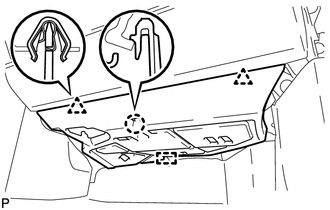
Disengage the 2 clips, claw and guide.
-
Disengage the clamp.
-
Disconnect the connector and remove the No. 2 instrument panel under cover sub-assembly.
-
-
REMOVE NO. 2 INSTRUMENT PANEL UNDER COVER SUB-ASSEMBLY (for RHD)
-
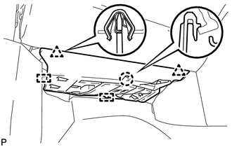
Disengage the 2 clips, claw and 2 guides.
-
Disengage the clamp.
-
Disconnect the connector and remove the No. 2 instrument panel under cover sub-assembly.
-
-
REMOVE FRONT DOOR SCUFF PLATE RH
Tech Tips
Use the same procedure described for the LH side Click here.
-
REMOVE COWL SIDE TRIM SUB-ASSEMBLY RH
Tech Tips
Use the same procedure described for the LH side Click here.
-
REMOVE LOWER NO. 2 INSTRUMENT PANEL AIRBAG ASSEMBLY
-
REMOVE GLOVE COMPARTMENT DOOR ASSEMBLY
-
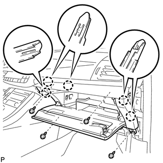
Remove the 4 screws <C>.
-
Disengage the 5 claws.
-
Disengage the clamp.
-
Disconnect the connector and remove the glove compartment door assembly.
-
-
REMOVE FRONT PILLAR GARNISH RH
Tech Tips
Use the same procedure described for the LH side.
-
REMOVE NO. 3 INSTRUMENT CLUSTER FINISH PANEL GARNISH (for Metal Finish Panel and Urethane Panel)
-
Disengage the 5 clips and remove the No. 3 instrument cluster finish panel garnish.
-
-
REMOVE NO. 3 INSTRUMENT CLUSTER FINISH PANEL GARNISH (for Wood Panel and Bamboo Panel)
-
Disengage the 4 clips and remove the No. 3 instrument cluster finish panel garnish.
-
-
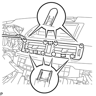
REMOVE NO. 2 INSTRUMENT PANEL REGISTER ASSEMBLY
-
Using a moulding remover, disengage the 7 claws and 3 guides, and remove the No. 2 instrument panel register assembly.
-
-
REMOVE NO. 2 DEFROSTER NOZZLE OPENING PLATE
-
Using a moulding remover, disengage the 4 claws and remove the No. 2 defroster nozzle opening plate.
-
-
REMOVE NO. 1 INSTRUMENT PANEL SPEAKER PANEL SUB-ASSEMBLY
Tech Tips
Use the same procedure described for the LH side.
-
REMOVE FRONT NO. 2 SPEAKER ASSEMBLY (w/ Front No. 2 Speaker)
Tech Tips
Use the same procedure described for the LH side.
-
REMOVE NO. 1 SPEAKER OPENING COVER ASSEMBLY
-

Using a moulding remover, disengage the 4 clips and remove the No. 1 speaker opening cover assembly.
-
-
REMOVE FRONT NO. 4 SPEAKER ASSEMBLY (w/ Front Center Speaker)
-
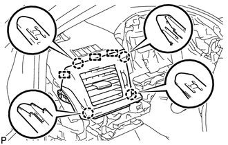
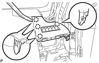
REMOVE CENTER INSTRUMENT PANEL REGISTER ASSEMBLY
-
Using a moulding remover, disengage the 8 claws and 3 guides.
-
Disconnect the connector and remove the center instrument panel register assembly.
-
-
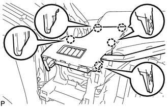
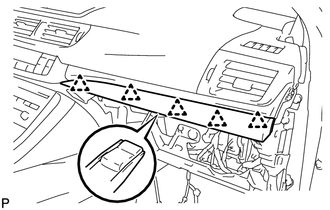
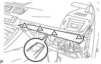
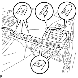
REMOVE INSTRUMENT CLUSTER FINISH PANEL SUB-ASSEMBLY (w/ Instrument Panel Box)
-
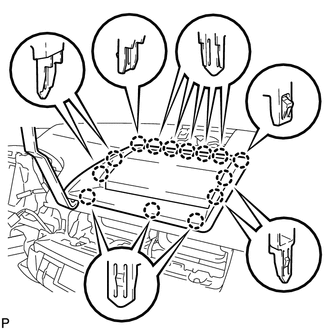
Using a moulding remover, disengage the 14 claws.
-
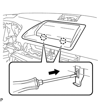
Using a screwdriver, disengage the 2 claws and remove the instrument cluster finish panel sub-assembly as shown in the illustration.
-
-
REMOVE INSTRUMENT CLUSTER FINISH PANEL SUB-ASSEMBLY (w/ Navigation System)
-
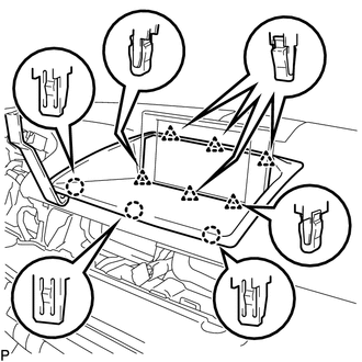
Using a moulding remover, disengage the 3 claws and 6 clips.
-
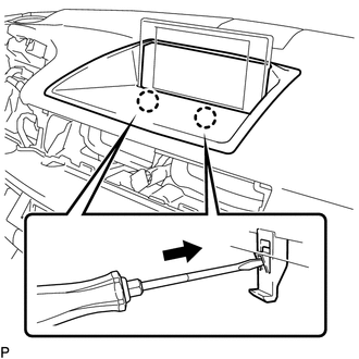
Using a screwdriver, disengage the 2 claws and remove the instrument cluster finish panel sub-assembly as shown in the illustration.
-
-
REMOVE MULTI-DISPLAY (w/ Navigation System)
-
DISCONNECT NO. 3 INSTRUMENT PANEL WIRE
-
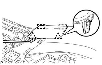
REMOVE UPPER INSTRUMENT PANEL ASSEMBLY
-
Disconnect each connector.
-
Disengage the clamp.
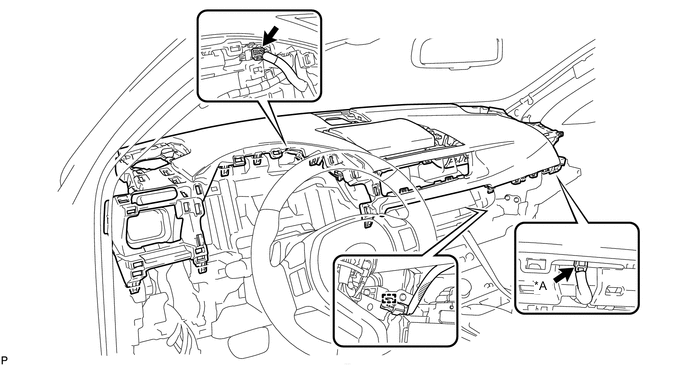
Text in Illustration *A w/ Navigation System - - -
Remove the 2 bolts <A> and 2 screws <B>.
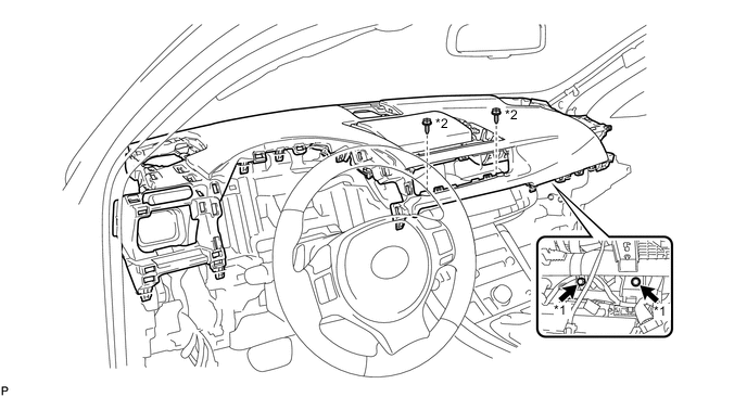
Text in Illustration *1 Bolt <A> *2 Screw <B> -
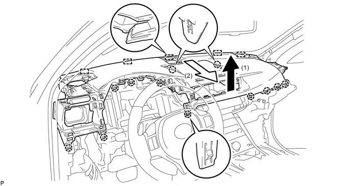
Disengage the 12 claws.
-
Disengage the 5 guides and remove the upper instrument panel assembly as shown in the illustration.
Note
Do not damage the upper instrument panel assembly.
-