POWER OUTLET SOCKET REMOVAL
PROCEDURE
-
REMOVE CENTER INSTRUMENT PANEL REGISTER ASSEMBLY (for Front Side)
-
REMOVE INSTRUMENT CLUSTER FINISH PANEL SUB-ASSEMBLY (for Front Side)
-
REMOVE INSTRUMENT PANEL BOX ASSEMBLY (for Front Side)
-
Open the instrument panel box assembly door.
-
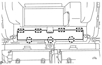
Disengage the 3 claws and 4 guides, and remove the instrument panel finish panel end.
-
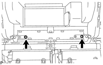
Remove the 2 screws.
-
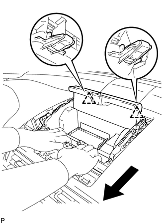
Disengage the 2 clips as shown in the illustration.
-
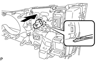
Using a screwdriver, disengage the 2 clamps.
-
Disconnect the connector and remove the instrument panel box assembly.
-
-
REMOVE NO. 3 POWER OUTLET SOCKET ASSEMBLY (for Front Side)
-
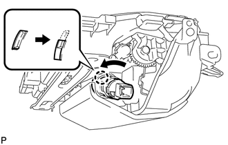
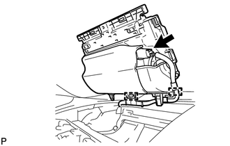
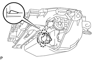
Turn the No. 3 power outlet socket assembly in the direction shown in the illustration to disengage the claw.
-
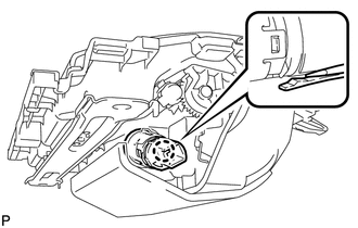
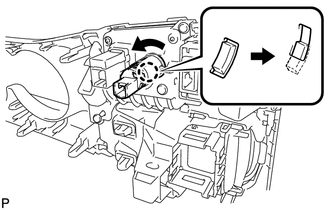
Using a screwdriver, disengage the claw, and then push in the No. 3 power outlet socket assembly until the protrusion of the No. 3 power outlet socket assembly comes into contact with the No. 2 power outlet socket cover.
-
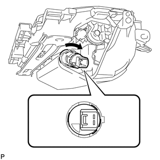
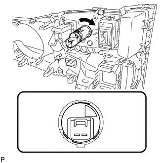
As shown in the illustration, align the protrusion of the No. 3 power outlet socket assembly and the notch of the No. 2 power outlet socket cover.
-
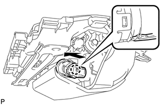
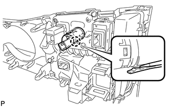
Using a screwdriver, disengage the claw and remove the No. 3 power outlet socket assembly from the No. 2 power outlet socket cover.
-
-
REMOVE NO. 2 POWER OUTLET SOCKET COVER (for Front Side)
-
Disengage the 2 claws and remove the No. 2 power outlet socket cover.
-
-
REMOVE LOWER CENTER INSTRUMENT PANEL FINISH PANEL (for Rear Side)
-
REMOVE UPPER NO. 2 CONSOLE PANEL GARNISH (for Rear Side)
-
REMOVE UPPER NO. 1 CONSOLE PANEL GARNISH (for Rear Side)
-
REMOVE UPPER CONSOLE PANEL SUB-ASSEMBLY (for Rear Side)
-
REMOVE NO. 3 POWER OUTLET SOCKET ASSEMBLY (for Rear Side)
-
Turn the No. 3 power outlet socket assembly in the direction shown in the illustration to disengage the claw.
-
Using a screwdriver, disengage the claw, and then push in the No. 3 power outlet socket assembly until the protrusion of the No. 3 power outlet socket assembly comes into contact with the No. 2 power outlet socket cover.
-
As shown in the illustration, align the protrusion of the No. 3 power outlet socket assembly and the notch of the No. 2 power outlet socket cover.
-
Using a screwdriver, disengage the claw and remove the No. 3 power outlet socket assembly from the No. 2 power outlet socket cover.
-
-
REMOVE NO. 2 POWER OUTLET SOCKET COVER (for Rear Side)
-

Disengage the 2 claws and remove the No. 2 power outlet socket cover.
-