FRONT POWER SEAT CONTROL SYSTEM(w/ Memory) Power Seat does not Return to Memorized Position
DESCRIPTION
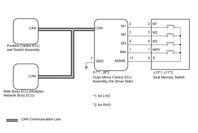
When any of the M1, M2 or M3 switches is pressed, the outer mirror control ECU assembly (for driver side) sends a switch signal to the main body ECU (multiplex network body ECU) via CAN communication. Then, the main body ECU (multiplex network body ECU) sends a recall request signal to the position control ECU and switch assembly. The position control ECU and switch assembly operates each motor to achieve each memorized position value.
WIRING DIAGRAM
CAUTION / NOTICE / HINT
Note
Inspect the fuses for circuits related to this system before performing the following inspection procedure.
PROCEDURE
-
CHECK CAN COMMUNICATION SYSTEM
-
Use the intelligent tester to check if the CAN communication system is functioning normally Click here.
OK CAN communication DTC is not output.
NG 
GO TO CAN COMMUNICATION SYSTEM Click here
OK 
-
-
CHECK FRONT POWER SEAT CONTROL SYSTEM
-
Check that each function of the power seat operates normally by using the switches on the power seat switch Click here.
OK Each function of the power seat operates normally using the switches on the power seat switch.
NG
GO TO PROBLEM SYMPTOMS TABLE Click here
OK
-
-
CHECK SEAT POSITION MEMORY FUNCTION
-
Perform a memory operation and check that the buzzer sounds to indicate the completion of the memory operation Click here.
Note
-
The seat position will not be recorded if the SET switch and 2 or more of the memory switches (for example, M1 switch and M2 switch) are pressed simultaneously.
-
If a memorizing operation has failed, release all switches. The seat memory function does not operate unless the switches are released.
OK Seat position memory function is normal. -
NG
GO TO OTHER DIAGNOSIS PROCEDURE (Power Seat Position is not Memorized) Click here
OK
-
-
CHECK SEAT POSITION RESTORING FUNCTION
-
Under each of the following conditions, check that the seat restoring function operates by pressing the M1 switch, M2 switch or M3 switch Click here.
-
Power switch is off.
-
The power switch is on (IG), and park (P) is selected.*1
-
The power switch is off within 180 seconds after the driver door is closed and opened.*2
-
The power switch is off within 60 seconds after the driver door is opened and closed.*3
Result Result Proceed to Seat restoring function does not operate at all. A Seat restoring function does not operate when the condition is *1. B
-
Seat restoring function does not operate when the condition is *2.
-
Seat restoring function does not operate when the condition is *3.
C -
B 
READ VALUE USING INTELLIGENT TESTER (PARK (P) STATE) Click here
C
READ VALUE USING INTELLIGENT TESTER (DRIVER DOOR COURTESY SWITCH) Click here
A
-
-
READ VALUE USING INTELLIGENT TESTER (SEAT POSITION MEMORY)
-
Perform the seat position memorized function for the M1, M2 and M3 switch Click here.
-
Connect the intelligent tester to the DLC3.
-
Turn the power switch on (IG).
-
Turn the intelligent tester on.
-
Enter the following menus: Body / Driver Seat / Data List.
-
Read the Data List according to the display on the intelligent tester.
Driver Seat (Position Control ECU and Switch Assembly) Tester Display Measurement Item/Range Normal Condition Diagnostic Note Seat Memory No1 Seat position memorized with M1 switch / Mem or Not Mem Mem: Memorized
Not Mem: Not memorized
- Seat Memory No2 Seat position memorized with M2 switch / Mem or Not Mem Mem: Memorized
Not Mem: Not memorized
- Seat Memory No3 Seat position memorized with M3 switch / Mem or Not Mem Mem: Memorized
Not Mem: Not memorized
- OK Mem appears on the intelligent tester screen.
NG
GO TO OTHER DIAGNOSIS PROCEDURE (Power Seat Position is not Memorized) Click here
OK
-
-
REPLACE OUTER MIRROR CONTROL ECU ASSEMBLY (for Driver Side)
-
Replace the outer mirror control ECU assembly (for driver side) Click here.
NEXT
-
-
CHECK SEAT POSITION RESTORING FUNCTION
-
Perform a seat position restoring function Click here.
-
Check that the buzzer sounds for 0.1 seconds and the seat automatically moves to the memorized position.
Note
-
The seat position will not return to the memorized position if 2 or more of the seat memory switches (for example, M1 switch and M2 switch) are pressed simultaneously.
-
If a restoring operation has failed, release all switches. The seat memory restoring function does not operate unless the switches are released.
OK Seat position restoring function operates normally. -
OK
END (OUTER MIRROR CONTROL ECU (for Driver Side) WAS DEFECTIVE)
NG
-
-
REPLACE POSITION CONTROL ECU AND SWITCH ASSEMBLY
-
Replace the position control ECU and switch assembly Click here.
NEXT
-
-
CHECK SEAT POSITION RESTORING FUNCTION
-
Perform a seat position memory function Click here.
-
Perform a seat position restoring function Click here.
-
Check that the buzzer sounds for 0.1 seconds and the seat automatically moves to the memorized position.
Note
-
The seat position will not return to the memorized position if 2 or more of the seat memory switches (for example, M1 switch and M2 switch) are pressed simultaneously.
-
If a restoring operation has failed, release all switches. The seat memory restoring function does not operate unless the switches are released.
OK Seat position restoring function operates normally. -
OK
END (POSITION CONTROL ECU AND SWITCH ASSEMBLY WAS DEFECTIVE)
NG
REPLACE MAIN BODY ECU (MULTIPLEX NETWORK BODY ECU) Click here
-
-
READ VALUE USING INTELLIGENT TESTER (PARK (P) STATE)
-
Connect the intelligent tester to the DLC3.
-
Turn the power switch on (IG).
-
Turn the intelligent tester on.
-
Enter the following menus: Body / Driver Seat / Data List.
-
Read the Data List according to the display on the intelligent tester.
Driver Seat (Position Control ECU and Switch Assembly) Tester Connection Measurement Item/Range Normal Condition Diagnostic Note P Switch Park (P) state signal / ON or OFF ON: Park (P) selected
OFF: Shift state other than park (P) selected
- OK On the intelligent tester screen, the item changes between ON and OFF according to the above.
OK
REPLACE POSITION CONTROL ECU AND SWITCH ASSEMBLY Click here
NG
GO TO ELECTRONIC SHIFT LEVER SYSTEM Click here
-
-
READ VALUE USING INTELLIGENT TESTER (DRIVER DOOR COURTESY SWITCH)
-
Connect the intelligent tester to the DLC3.
-
Turn the power switch on (IG).
-
Turn the intelligent tester on.
-
Enter the following menus: Body / Main Body / Data List.
-
Read the Data List according to the display on the intelligent tester.
Main Body (Main Body ECU (Multiplex Network Body ECU)) Tester Connection Measurement Item/Range Normal Condition Diagnostic Note FR Door Courtesy*1 Front door courtesy light switch assembly signal / ON or OFF ON: Driver door open
OFF: Driver door closed
- FL Door Courtesy*2 Front door courtesy light switch assembly signal / ON or OFF ON: Driver door open
OFF: Driver door closed
-
-
*1: for RHD
-
*2: for LHD
OK On the intelligent tester screen, the item changes between ON and OFF according to the above. -
OK
REPLACE POSITION CONTROL ECU AND SWITCH ASSEMBLY Click here
NG
GO TO LIGHTING SYSTEM (Door Courtesy Switch Circuit) Click here
-