PRE-COLLISION SYSTEM, Diagnostic DTC:C1A4B
| DTC Code | DTC Name |
|---|---|
| C1A4B | Stop Light Relay Circuit |
DESCRIPTION
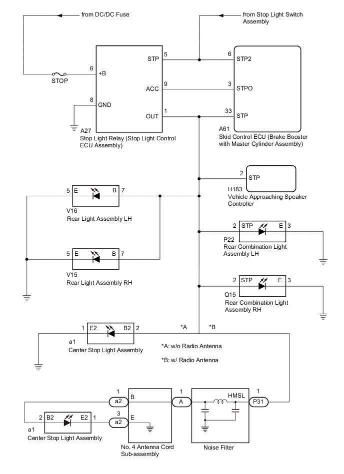
The skid control ECU (brake booster with master cylinder assembly) sends a stop light operation request signal to the stop light relay (stop light control ECU assembly). If the skid control ECU (brake booster with master cylinder assembly) detects a malfunction in the stop light relay (stop light control ECU assembly) circuit, the driving support ECU assembly stores DTC C1A4B.
| DTC No. | Detection Item | DTC Detection Condition | Trouble Area |
|---|---|---|---|
| C1A4B | Stop Light Relay Circuit | Both of the following conditions are met:
Tech Tips The skid control ECU (brake booster with master cylinder assembly) will detect a stop light relay circuit malfunction if any of the following conditions are met:
|
|
WIRING DIAGRAM
CAUTION / NOTICE / HINT
Note
-
Inspect the fuses for circuits related to this system before performing the following procedure.
-
Make sure that there is no looseness at the locking part and the connecting part of the connector.
-
Check both the connector case and the terminals for deformation and corrosion.
PROCEDURE
-
INSPECT TERMINAL VOLTAGE (SKID CONTROL ECU (BRAKE BOOSTER WITH MASTER CYLINDER ASSEMBLY) CONNECTOR)
-
Turn the power switch off.
-
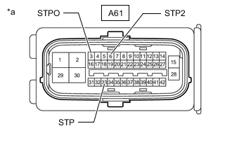
*a Front view of wire harness connector
(to Skid Control ECU (Brake Booster with Master Cylinder Assembly))
Disconnect the A61 skid control ECU (brake booster with master cylinder assembly) connector.
-
Measure the voltage according to the value(s) in the table below.
Standard Voltage Tester Connection Condition Specified Condition A61-6 (STP2) - Body ground Brake pedal depressed 11 to 14 V Brake pedal released Below 1.5 V A61-3 (STPO) - Body ground Always 11 to 14 V A61-33 (STP) - Body ground Brake pedal depressed 11 to 14 V Brake pedal released Below 1.5 V -
Connect the A61 skid control ECU (brake booster with master cylinder assembly) connector.
Result Result Proceed to The voltage is as specified for every terminal. A Only the voltage at terminal STP2 is not as specified. B Only the voltage at terminal STPO is not as specified. C Only the voltage at terminal STP is not as specified. D The voltage at both terminal STPO and terminal STP are not as specified. E
B 
REPAIR OR REPLACE HARNESS OR CONNECTOR
C 
CHECK WIRE HARNESS AND CONNECTOR (SKID CONTROL ECU (BRAKE BOOSTER WITH MASTER CYLINDER ASSEMBLY) - STOP LIGHT RELAY (STOP LIGHT CONTROL ECU ASSEMBLY)) Click here
D
INSPECT TERMINAL VOLTAGE (SKID CONTROL ECU (BRAKE BOOSTER WITH MASTER CYLINDER ASSEMBLY) CONNECTOR) Click here
E
CHECK WIRE HARNESS AND CONNECTOR (SKID CONTROL ECU (BRAKE BOOSTER WITH MASTER CYLINDER ASSEMBLY) - STOP LIGHT RELAY (STOP LIGHT CONTROL ECU ASSEMBLY)) Click here
A 
-
-
PERFORM ACTIVE TEST USING GTS (STOP LIGHT RELAY)
-
Connect the GTS to the DLC3.
-
Turn the power switch on (IG).
-
Turn the GTS on.
-
Enter the following menus: Chassis / ABS/VSC/TRC / Active Test.
-
According to the display on the GTS, perform the Active Test Stop Light Relay.
Chassis > ABS/VSC/TRC > Active Test Tester Display Measurement Item Control Range Diagnostic Note Stop Light Relay Stop light relay (Stop light control ECU assembly) ON / OFF Stop lights come on OK The stop lights turn on and off correctly in response to the operation of the Active Test. Result Proceed to OK NG
NG
INSPECT STOP LIGHT RELAY (STOP LIGHT CONTROL ECU ASSEMBLY) Click here
OK
-
-
CHECK FOR DTCS (PRE-COLLISION SYSTEM)
-
Connect the GTS to the DLC3.
-
Turn the power switch on (IG).
-
Turn the GTS on.
-
Enter the following menus: Body Electrical / Pre-Collision 2 / Trouble Codes.
-
Clear the DTCs.
-
Enter the following menus: Chassis / ABS/VSC/TRC / Active Test.
-
According to the display on the GTS, perform the Active Test Stop Light Relay.
Chassis > ABS/VSC/TRC > Active Test Tester Display Measurement Item Control Range Diagnostic Note Stop Light Relay Stop light relay (Stop light control ECU assembly) ON / OFF Stop lights come on -
Enter the following menus: Body Electrical / Pre-Collision 2 / Trouble Codes.
-
Check for DTCs.
OK DTC C1A4B is not output Result Proceed to OK NG
OK
USE SIMULATION METHOD TO CHECK Click here
NG
REPLACE SKID CONTROL ECU (BRAKE BOOSTER WITH MASTER CYLINDER ASSEMBLY) for LHD: Click here for RHD: Click here
-
-
INSPECT STOP LIGHT RELAY (STOP LIGHT CONTROL ECU ASSEMBLY)
-
Inspect the stop light relay (stop light control ECU assembly).
OK The stop light relay (stop light control ECU assembly) is normal. Result Proceed to OK NG
OK
REPLACE SKID CONTROL ECU (BRAKE BOOSTER WITH MASTER CYLINDER ASSEMBLY) for LHD: Click here for RHD: Click here
NG
REPLACE STOP LIGHT RELAY (STOP LIGHT CONTROL ECU ASSEMBLY) Click here
-
-
CHECK WIRE HARNESS AND CONNECTOR (SKID CONTROL ECU (BRAKE BOOSTER WITH MASTER CYLINDER ASSEMBLY) - STOP LIGHT RELAY (STOP LIGHT CONTROL ECU ASSEMBLY))
-
Turn the power switch off.
-
Disconnect the A27 stop light relay (stop light control ECU assembly) connector.
-
Disconnect the A61 skid control ECU (brake booster with master cylinder assembly) connector.
-
Measure the resistance according to the value(s) in the table below.
Standard Resistance Tester Connection Condition Specified Condition A61-3 (STPO) - A27-9 (ACC) Always Below 1 Ω -
Connect the A61 skid control ECU (brake booster with master cylinder assembly) connector.
-
Connect the A27 stop light relay (stop light control ECU assembly) connector.
Result Proceed to OK NG
OK
REPLACE STOP LIGHT RELAY (STOP LIGHT CONTROL ECU ASSEMBLY) Click here
NG
REPAIR OR REPLACE HARNESS OR CONNECTOR
-
-
INSPECT TERMINAL VOLTAGE (SKID CONTROL ECU (BRAKE BOOSTER WITH MASTER CYLINDER ASSEMBLY) CONNECTOR)
-
Turn the power switch off.
-
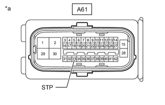
*a Front view of wire harness connector
(to Skid Control ECU (Brake Booster with Master Cylinder Assembly))
Disconnect the A61 skid control ECU (brake booster with master cylinder assembly) connector.
-
Measure the voltage according to the value(s) in the table below.
Standard Voltage Tester Connection Condition Specified Condition A61-33 (STP) - Body ground Brake pedal released Below 1.5 V -
Connect the A61 skid control ECU (brake booster with master cylinder assembly) connector.
Result Proceed to OK NG
NG
CHECK WIRE HARNESS AND CONNECTOR (SKID CONTROL ECU (BRAKE BOOSTER WITH MASTER CYLINDER ASSEMBLY) - STOP LIGHT RELAY (STOP LIGHT CONTROL ECU ASSEMBLY)) Click here
OK
-
-
CHECK WIRE HARNESS AND CONNECTOR (SKID CONTROL ECU (BRAKE BOOSTER WITH MASTER CYLINDER ASSEMBLY) - VEHICLE APPROACHING SPEAKER CONTROLLER)
-
Disconnect the A61 skid control ECU (brake booster with master cylinder assembly) connector.
-
Disconnect the H183 vehicle approaching speaker controller connector.
-
Measure the voltage according to the value(s) in the table below.
Standard Voltage Tester Connection Condition Specified Condition A61-33 (STP) - Body ground Brake pedal depressed 11 to 14 V -
Connect the H183 vehicle approaching speaker controller connector.
-
Connect the A61 skid control ECU (brake booster with master cylinder assembly) connector.
Result Proceed to OK NG
OK
REPLACE VEHICLE APPROACHING SPEAKER CONTROLLER Click here
NG
-
-
CHECK WIRE HARNESS AND CONNECTOR (SKID CONTROL ECU (BRAKE BOOSTER WITH MASTER CYLINDER ASSEMBLY) - REAR COMBINATION LIGHT ASSEMBLY LH)
-
Disconnect the A61 skid control ECU (brake booster with master cylinder assembly) connector.
-
Disconnect the P22 rear combination light assembly LH connector.
-
Measure the voltage according to the value(s) in the table below.
Standard Voltage Tester Connection Condition Specified Condition A61-33 (STP) - Body ground Brake pedal depressed 11 to 14 V -
Connect the P22 rear combination light assembly LH connector.
-
Connect the A61 skid control ECU (brake booster with master cylinder assembly) connector.
Result Proceed to OK NG
OK
REPLACE REAR COMBINATION LIGHT ASSEMBLY LH Click here
NG
-
-
CHECK WIRE HARNESS AND CONNECTOR (SKID CONTROL ECU (BRAKE BOOSTER WITH MASTER CYLINDER ASSEMBLY) - REAR COMBINATION LIGHT ASSEMBLY RH)
-
Disconnect the A61 skid control ECU (brake booster with master cylinder assembly) connector.
-
Disconnect the Q15 rear combination light assembly RH connector.
-
Measure the voltage according to the value(s) in the table below.
Standard Voltage Tester Connection Condition Specified Condition A61-33 (STP) - Body ground Brake pedal depressed 11 to 14 V -
Connect the Q15 rear combination light assembly RH connector.
-
Connect the A61 skid control ECU (brake booster with master cylinder assembly) connector.
Result Proceed to OK NG
OK
REPLACE REAR COMBINATION LIGHT ASSEMBLY RH Click here
NG
-
-
CHECK WIRE HARNESS AND CONNECTOR (SKID CONTROL ECU (BRAKE BOOSTER WITH MASTER CYLINDER ASSEMBLY) - REAR LIGHT ASSEMBLY LH)
-
Disconnect the A61 skid control ECU (brake booster with master cylinder assembly) connector.
-
Disconnect the V16 rear light assembly LH connector.
-
Measure the voltage according to the value(s) in the table below.
Standard Voltage Tester Connection Condition Specified Condition A61-33 (STP) - Body ground Brake pedal depressed 11 to 14 V -
Connect the V16 rear light assembly LH connector.
-
Connect the A61 skid control ECU (brake booster with master cylinder assembly) connector.
Result Proceed to OK NG
OK
REPLACE REAR LIGHT ASSEMBLY LH Click here
NG
-
-
CHECK WIRE HARNESS AND CONNECTOR (SKID CONTROL ECU (BRAKE BOOSTER WITH MASTER CYLINDER ASSEMBLY) - REAR LIGHT ASSEMBLY RH)
-
Disconnect the A61 skid control ECU (brake booster with master cylinder assembly) connector.
-
Disconnect the V15 rear light assembly RH connector.
-
Measure the voltage according to the value(s) in the table below.
Standard Voltage Tester Connection Condition Specified Condition A61-33 (STP) - Body ground Brake pedal depressed 11 to 14 V -
Connect the V15 rear light assembly RH connector.
-
Connect the A61 skid control ECU (brake booster with master cylinder assembly) connector.
Result Result Proceed to OK A NG (w/o Radio Antenna) B NG (w/ Radio Antenna) C
A
REPLACE REAR LIGHT ASSEMBLY RH Click here
C
CHECK WIRE HARNESS AND CONNECTOR (SKID CONTROL ECU (BRAKE BOOSTER WITH MASTER CYLINDER ASSEMBLY) - NOISE FILTER) Click here
B
-
-
CHECK WIRE HARNESS AND CONNECTOR (SKID CONTROL ECU (BRAKE BOOSTER WITH MASTER CYLINDER ASSEMBLY) - CENTER STOP LIGHT ASSEMBLY)
-
Disconnect the A61 skid control ECU (brake booster with master cylinder assembly) connector.
-
Disconnect the a1 center stop light assembly connector.
-
Measure the voltage according to the value(s) in the table below.
Standard Voltage Tester Connection Condition Specified Condition A61-33 (STP) - Body ground Brake pedal depressed 11 to 14 V -
Connect the a1 center stop light assembly connector.
-
Connect the A61 skid control ECU (brake booster with master cylinder assembly) connector.
Result Proceed to OK NG
OK
REPLACE CENTER STOP LIGHT ASSEMBLY Click here
NG
GO TO STEP 17 Click here
-
-
CHECK WIRE HARNESS AND CONNECTOR (SKID CONTROL ECU (BRAKE BOOSTER WITH MASTER CYLINDER ASSEMBLY) - NOISE FILTER)
-
Disconnect the A61 skid control ECU (brake booster with master cylinder assembly) connector.
-
Disconnect the P31 noise filter connector.
-
Measure the voltage according to the value(s) in the table below.
Standard Voltage Tester Connection Condition Specified Condition A61-33 (STP) - Body ground Brake pedal depressed 11 to 14 V -
Connect the P31 noise filter connector.
-
Connect the A61 skid control ECU (brake booster with master cylinder assembly) connector.
Result Proceed to OK NG
NG
CHECK WIRE HARNESS AND CONNECTOR (SKID CONTROL ECU (BRAKE BOOSTER WITH MASTER CYLINDER ASSEMBLY) - STOP LIGHT RELAY (STOP LIGHT CONTROL ECU ASSEMBLY)) Click here
OK
-
-
CHECK WIRE HARNESS AND CONNECTOR (SKID CONTROL ECU (BRAKE BOOSTER WITH MASTER CYLINDER ASSEMBLY) - CENTER STOP LIGHT ASSEMBLY)
-
Disconnect the A61 skid control ECU (brake booster with master cylinder assembly) connector.
-
Disconnect the a1 center stop light assembly connector.
-
Measure the voltage according to the value(s) in the table below.
Standard Voltage Tester Connection Condition Specified Condition A61-33 (STP) - Body ground Brake pedal depressed 11 to 14 V -
Connect the a1 center stop light assembly connector.
-
Connect the A61 skid control ECU (brake booster with master cylinder assembly) connector.
Result Proceed to OK NG
OK
REPLACE CENTER STOP LIGHT ASSEMBLY Click here
NG
-
-
CHECK WIRE HARNESS AND CONNECTOR (NO. 4 ANTENNA CORD SUB-ASSEMBLY - CENTER STOP LIGHT ASSEMBLY)
-
Disconnect the a2 No. 4 antenna cord sub-assembly connector.
-
Disconnect the a1 center stop light assembly connector.
-
Measure the resistance according to the value(s) in the table below.
Standard Resistance Tester Connection Condition Specified Condition a2-1 (B) - Body ground Always 10 kΩ or higher a1-2 (B2) - Body ground Always 10 kΩ or higher -
Connect the a1 center stop light assembly connector.
-
Connect the a2 No. 4 antenna cord sub-assembly connector.
Result Proceed to OK NG
NG
REPAIR OR REPLACE HARNESS OR CONNECTOR (NO. 4 ANTENNA CORD SUB-ASSEMBLY - CENTER STOP LIGHT ASSEMBLY)
OK
-
-
INSPECT NOISE FILTER
-
Disconnect the P31 and A noise filter connector.
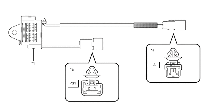
*1 Noise Filter - - *a Component without harness connected - - -
Measure the resistance according to the value(s) in the table below.
Standard Resistance Tester Connection Condition Specified Condition P31-1 (HMSL) - Body ground Always 10 kΩ or higher A-1 - Body ground Always 10 kΩ or higher -
Connect the P31 and A noise filter connector.
Result Proceed to OK NG
OK
REPLACE NO. 4 ANTENNA CORD SUB-ASSEMBLY Click here
NG
REPLACE NOISE FILTER
-
-
CHECK WIRE HARNESS AND CONNECTOR (SKID CONTROL ECU (BRAKE BOOSTER WITH MASTER CYLINDER ASSEMBLY) - STOP LIGHT RELAY (STOP LIGHT CONTROL ECU ASSEMBLY))
-
Turn the power switch off.
-
Disconnect the A61 skid control ECU (brake booster with master cylinder assembly) connector.
-
Disconnect the A27 stop light relay (stop light control ECU assembly) connector.
-
Measure the resistance according to the value(s) in the table below.
Standard Resistance Tester Connection Condition Specified Condition A27-5 (STP) - A61-6 (STP2) Always Below 1 Ω A27-1 (OUT) - A61-33 (STP) Always Below 1 Ω A27-1 (OUT) or A61-33 (STP) - Body ground Always 10 kΩ or higher -
Connect the A27 stop light relay (stop light control ECU assembly) connector.
-
Connect the A61 skid control ECU (brake booster with master cylinder assembly) connector.
Result Proceed to OK NG
OK
REPLACE STOP LIGHT RELAY (STOP LIGHT CONTROL ECU ASSEMBLY) Click here
NG
REPAIR OR REPLACE HARNESS OR CONNECTOR
-
-
CHECK WIRE HARNESS AND CONNECTOR (SKID CONTROL ECU (BRAKE BOOSTER WITH MASTER CYLINDER ASSEMBLY) - STOP LIGHT RELAY (STOP LIGHT CONTROL ECU ASSEMBLY))
-
Disconnect the A61 skid control ECU (brake booster with master cylinder assembly) connector.
-
Disconnect the A27 stop light relay (stop light control ECU assembly) connector.
-
Measure the voltage according to the value(s) in the table below.
Standard Voltage Tester Connection Condition Specified Condition A61-33 (STP) - Body ground Brake pedal released Below 1.5 V -
Connect the A27 stop light relay (stop light control ECU assembly) connector.
-
Connect the A61 skid control ECU (brake booster with master cylinder assembly) connector.
Result Proceed to OK NG
OK
REPLACE STOP LIGHT RELAY (STOP LIGHT CONTROL ECU ASSEMBLY) Click here
NG
-
-
CHECK WIRE HARNESS AND CONNECTOR (SKID CONTROL ECU (BRAKE BOOSTER WITH MASTER CYLINDER ASSEMBLY) - VEHICLE APPROACHING SPEAKER CONTROLLER)
-
Disconnect the A61 skid control ECU (brake booster with master cylinder assembly) connector.
-
Disconnect the H183 vehicle approaching speaker controller connector.
-
Measure the voltage according to the value(s) in the table below.
Standard Voltage Tester Connection Condition Specified Condition A61-33 (STP) - Body ground Brake pedal released Below 1.5 V -
Connect the H183 vehicle approaching speaker controller connector.
-
Connect the A61 skid control ECU (brake booster with master cylinder assembly) connector.
Result Proceed to OK NG
OK
REPLACE VEHICLE APPROACHING SPEAKER CONTROLLER Click here
NG
-
-
CHECK WIRE HARNESS AND CONNECTOR (SKID CONTROL ECU (BRAKE BOOSTER WITH MASTER CYLINDER ASSEMBLY) - REAR COMBINATION LIGHT ASSEMBLY LH)
-
Disconnect the A61 skid control ECU (brake booster with master cylinder assembly) connector.
-
Disconnect the P22 rear combination light assembly LH connector.
-
Measure the voltage according to the value(s) in the table below.
Standard Voltage Tester Connection Condition Specified Condition A61-33 (STP) - Body ground Brake pedal released Below 1.5 V -
Connect the P22 rear combination light assembly LH connector.
-
Connect the A61 skid control ECU (brake booster with master cylinder assembly) connector.
Result Proceed to OK NG
OK
REPLACE REAR COMBINATION LIGHT ASSEMBLY LH Click here
NG
-
-
CHECK WIRE HARNESS AND CONNECTOR (SKID CONTROL ECU (BRAKE BOOSTER WITH MASTER CYLINDER ASSEMBLY) - REAR COMBINATION LIGHT ASSEMBLY RH)
-
Disconnect the A61 skid control ECU (brake booster with master cylinder assembly) connector.
-
Disconnect the Q15 rear combination light assembly RH connector.
-
Measure the voltage according to the value(s) in the table below.
Standard Voltage Tester Connection Condition Specified Condition A61-33 (STP) - Body ground Brake pedal released Below 1.5 V -
Connect the Q15 rear combination light assembly RH connector.
-
Connect the A61 skid control ECU (brake booster with master cylinder assembly) connector.
Result Proceed to OK NG
OK
REPLACE REAR COMBINATION LIGHT ASSEMBLY RH Click here
NG
-
-
CHECK WIRE HARNESS AND CONNECTOR (SKID CONTROL ECU (BRAKE BOOSTER WITH MASTER CYLINDER ASSEMBLY) - REAR LIGHT ASSEMBLY LH)
-
Disconnect the A61 skid control ECU (brake booster with master cylinder assembly) connector.
-
Disconnect the V16 rear light assembly LH connector.
-
Measure the voltage according to the value(s) in the table below.
Standard Voltage Tester Connection Condition Specified Condition A61-33 (STP) - Body ground Brake pedal released Below 1.5 V -
Connect the V16 rear light assembly LH connector.
-
Connect the A61 skid control ECU (brake booster with master cylinder assembly) connector.
Result Proceed to OK NG
OK
REPLACE REAR LIGHT ASSEMBLY LH Click here
NG
-
-
CHECK WIRE HARNESS AND CONNECTOR (SKID CONTROL ECU (BRAKE BOOSTER WITH MASTER CYLINDER ASSEMBLY) - REAR LIGHT ASSEMBLY RH)
-
Disconnect the A61 skid control ECU (brake booster with master cylinder assembly) connector.
-
Disconnect the V15 rear light assembly RH connector.
-
Measure the voltage according to the value(s) in the table below.
Standard Voltage Tester Connection Condition Specified Condition A61-33 (STP) - Body ground Brake pedal released Below 1.5 V -
Connect the V15 rear light assembly RH connector.
-
Connect the A61 skid control ECU (brake booster with master cylinder assembly) connector.
Result Result Proceed to OK A NG (w/o Radio Antenna) B NG (w/ Radio Antenna) C
A
REPLACE REAR LIGHT ASSEMBLY RH Click here
C
CHECK WIRE HARNESS AND CONNECTOR (SKID CONTROL ECU (BRAKE BOOSTER WITH MASTER CYLINDER ASSEMBLY) - NOISE FILTER) Click here
B
-
-
CHECK WIRE HARNESS AND CONNECTOR (SKID CONTROL ECU (BRAKE BOOSTER WITH MASTER CYLINDER ASSEMBLY) - CENTER STOP LIGHT ASSEMBLY)
-
Disconnect the A61 skid control ECU (brake booster with master cylinder assembly) connector.
-
Disconnect the a1 center stop light assembly connector.
-
Measure the voltage according to the value(s) in the table below.
Standard Voltage Tester Connection Condition Specified Condition A61-33 (STP) - Body ground Brake pedal released Below 1.5 V -
Connect the a1 center stop light assembly connector.
-
Connect the A61 skid control ECU (brake booster with master cylinder assembly) connector.
Result Proceed to OK NG
OK
REPLACE CENTER STOP LIGHT ASSEMBLY Click here
NG
REPAIR OR REPLACE HARNESS OR CONNECTOR
-
-
CHECK WIRE HARNESS AND CONNECTOR (SKID CONTROL ECU (BRAKE BOOSTER WITH MASTER CYLINDER ASSEMBLY) - NOISE FILTER)
-
Disconnect the A61 skid control ECU (brake booster with master cylinder assembly) connector.
-
Disconnect the P31 noise filter connector.
-
Measure the voltage according to the value(s) in the table below.
Standard Voltage Tester Connection Condition Specified Condition A61-33 (STP) - Body ground Brake pedal released Below 1.5 V -
Connect the P31 noise filter connector.
-
Connect the A61 skid control ECU (brake booster with master cylinder assembly) connector.
Result Proceed to OK NG
NG
REPAIR OR REPLACE HARNESS OR CONNECTOR
OK
-
-
CHECK WIRE HARNESS AND CONNECTOR (SKID CONTROL ECU (BRAKE BOOSTER WITH MASTER CYLINDER ASSEMBLY) - CENTER STOP LIGHT ASSEMBLY)
-
Disconnect the A61 skid control ECU (brake booster with master cylinder assembly) connector.
-
Disconnect the a1 center stop light assembly connector.
-
Measure the voltage according to the value(s) in the table below.
Standard Voltage Tester Connection Condition Specified Condition A61-33 (STP) - Body ground Brake pedal released Below 1.5 V -
Connect the a1 center stop light assembly connector.
-
Connect the A61 skid control ECU (brake booster with master cylinder assembly) connector.
Result Proceed to OK NG
OK
REPLACE CENTER STOP LIGHT ASSEMBLY Click here
NG
-
-
CHECK WIRE HARNESS AND CONNECTOR (NO. 4 ANTENNA CORD SUB-ASSEMBLY - CENTER STOP LIGHT ASSEMBLY)
-
Disconnect the a2 No. 4 antenna cord sub-assembly connector.
-
Disconnect the a1 center stop light assembly connector.
-
Measure the voltage according to the value(s) in the table below.
Standard Voltage Tester Connection Condition Specified Condition a2-1 (B) - Body ground Always Below 1.5 V a1-2 (B2) - Body ground Always Below 1.5 V -
Connect the a1 center stop light assembly connector.
-
Connect the a2 No. 4 antenna cord sub-assembly connector.
Result Proceed to OK NG
NG
REPAIR OR REPLACE HARNESS OR CONNECTOR (NO. 4 ANTENNA CORD SUB-ASSEMBLY - CENTER STOP LIGHT ASSEMBLY)
OK
-
-
INSPECT NOISE FILTER
-
Disconnect the P31 and A noise filter connector.
*1 Noise Filter - - *a Component without harness connected - - -
Measure the voltage according to the value(s) in the table below.
Standard Voltage Tester Connection Condition Specified Condition P31-1 (HMSL) - Body ground Always Below 1.5 V A-1 - Body ground Always Below 1.5 V -
Connect the P31 and A noise filter connector.
Result Proceed to OK NG
OK
REPLACE NO. 4 ANTENNA CORD SUB-ASSEMBLY Click here
NG
REPLACE NOISE FILTER
-
-
CHECK WIRE HARNESS AND CONNECTOR (SKID CONTROL ECU (BRAKE BOOSTER WITH MASTER CYLINDER ASSEMBLY) - STOP LIGHT RELAY (STOP LIGHT CONTROL ECU ASSEMBLY))
-
Turn the power switch off.
-
Disconnect the A27 stop light relay (stop light control ECU assembly) connector.
-
Disconnect the A61 skid control ECU (brake booster with master cylinder assembly) connector.
-
Measure the resistance according to the value(s) in the table below.
Standard Resistance Tester Connection Condition Specified Condition A61-3 (STPO) or A27-9 (ACC) - Body ground Always 10 kΩ or higher -
Connect the A61 skid control ECU (brake booster with master cylinder assembly) connector.
-
Connect the A27 stop light relay (stop light control ECU assembly) connector.
Result Proceed to OK NG
NG
REPAIR OR REPLACE HARNESS OR CONNECTOR
OK
-
-
INSPECT STOP LIGHT RELAY (STOP LIGHT CONTROL ECU ASSEMBLY)
-
Inspect the stop light relay (stop light control ECU assembly).
OK The stop light relay (stop light control ECU assembly) is normal. Result Result Proceed to OK A NG (Stop light relay (stop light control ECU assembly)) B NG (Power source circuit or Body ground circuit) C
A
REPAIR OR REPLACE HARNESS OR CONNECTOR
B
REPLACE STOP LIGHT RELAY (STOP LIGHT CONTROL ECU ASSEMBLY) Click here
C
REPAIR OR REPLACE HARNESS OR CONNECTOR
-